
Annex 7 - Coordination of PPEaA and pre-fuses
A 7.1
Practical rules of application for the coordinated selection of PPEaA and backup fuse
The following discussion considers the rules to apply for a coordinated application of PPEaA in conjunction with the use of short-circuit protection devices in the form of fuses for the low voltage range in AC systems.
The rules of application are valid for 400 V systems (three-phase AC system) and standard exposure conditions:
| Working distance: | a = 300 mm |
|---|---|
| Transmission factor: | kT = 1 (small-scale installation volume). |
The rules of application exist in 3 different forms, which can be optionally applied:
A1: Selection matrix
A2: Minimum overcurrent factor
A3: Permissible NH fuse trip time.
They are distinguished by their degree of simplification, accuracy and the type of manual handling. Separate considerations for 3-pole and 2-pole short-circuits (arcing fault) are possible.
The prospective short-circuit current, unaffected by electric fault arcing (bolted short-circuit), serves merely as a respective input variable resulting from the short-circuit current calculation; it is to be set as the initial short-circuit AC current I"k ,max1.
A 7.2
Selection matrix
The selection diagram that follows is applicable for the different operating classes of NH fuses for 2-pole and 3-pole short-circuits:
| • | Fig. A 7-1 to A 7-4 | Line protection fuse, operating class NH gG |
|---|---|---|
| • | Fig. A 7-5 to A 7-6 | Transformer protection fuse, operating class NH gTr |
| • | Fig. A 7.7 | Safe-work fuse (operating class aR, gR, ...). |
The selection or examination of the circuit protector is facilitated by means of classification by fuse current rating and short-circuit current range in the form of a matrix (requirement: Standard exposure conditions). The smallest respective value of permissible short-circuit current (minimum short-circuit current) can be read out. This is required in order to achieve a level of protection with the PPEaA together with a specific fuse.
Permissible conditions (protection guaranteed) are marked respectively "green"; in contrast, the "red" fields depict inadmissible conditions (protection not warranted).
It should be noted in general that personal protection (prevention of skin burns) can be viewed as warranted under standard exposure conditions with short-circuit currents below 1 kA, independent of the rated current.
A 7.3
Line protection fuses
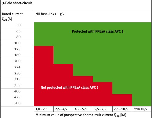
Fig. A 7-1
Selection of NH gG fuses with PPEaA in the Arc protection class APC 1 for 3-pole short-circuits
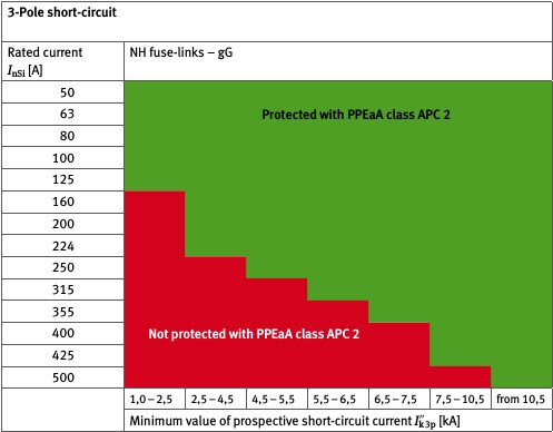
Fig. A 7-2
Selection of NH gG fuses with PPEaA in the Arc protection class APC 2 for 3-pole short-circuits
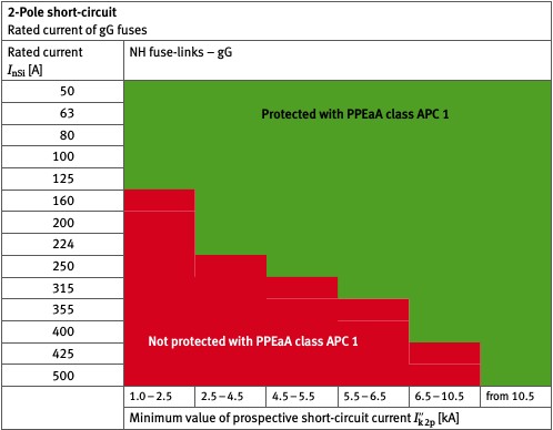
Fig. A 7-3
Selection of NH gG fuses with PPEaA in the Arc protection class APC 1 for 2-pole short-circuits
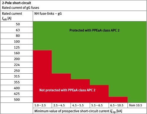
Fig. A 7-4
Selection of NH gG fuses with PPEaA in the Arc protection class APC 2 for 2-pole short-circuits
Example of NH gG line protection fuses:
The prospective 3-pole short-circuit current equals 3.614 kA. The range from 2.5 to 4.5 kA is appropriate; according to Fig. A 7-1, PPEaA in the Arc protection class APC 1 offers protection together with circuit protection with rated currents up to 200 A. If a 224 A fuse is present, then the PPEaA in the Arc protection class APC 1 does not provide sufficient protection anymore (according to Fig. A 7-2 in this case, sufficient protection will be provided using PPEaA in the Arc protection class APC 2).
A 7.4
Transformer protection fuses
With 3-pole short-circuits (under standard exposure conditions):
When using gTr fuses ≤ 250 kVA (361 A), protection is warranted only
through PPEaA in the Arc protection class APC 2 and
if the short-circuit current equals at least 7 kA.
When using gTr fuses > 250 kVA (361 A), neither PPEaA in the Arc protection class APC 1 nor PPEaA in the Arc protection class APC 2 will allow for protection to be realized.
For 2-pole short-circuits, the assertions on Fig. A 7-5 and Fig. A 7-6 apply.
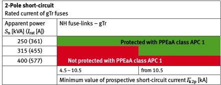
Fig. A 7-5
Selection of NH gTr fuses with PPEaA in the Arc protection class APC 1 for 2-pole
short-circuits
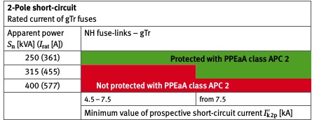
Fig. A 7-6
Selection of NH gTr fuses with PPEaA in the Arc protection class APC 2 for 2-pole
short-circuits
A 7.5
Safe-work fuses
The limits for the conditions, under which protection is provided through PPEaA in both Arc protection class APC 1 and Arc protection class APC 2 with both 2-pole and 3-pole short-circuits, are identical. This means that, within the permissible areas, sufficient protection is provided by PPEaA in the Arc protection class APC 1 and the use of PPEaA in the Arc protection class APC 2 will not enhance the scope of coverage. The selection diagram is applicable for both 2-pole as well as with 3-pole short-circuits. It should be noted here, that short-circuit currents for the same installation with 3-pole and 2-pole short-circuits are distinguished in level by a factor of 2 / √3 ≈ 1.155.
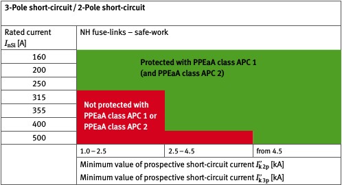
Fig. A 7-7
Selection of NH safe-work fuses with PPEaA in the Arc protection classes APC 1 and
APC 2 for 2-pole and 3-pole short-circuits
A 7.6
Minimum overcurrent factor
Table A 7-1 Minimum overcurrent factor
| NH fuse operating class | PPEaA Arc protection class | Minimum overcurrent factor kÜ mind | |
|---|---|---|---|
| 2-Pole short-circuit | 3-Pole short-circuit | ||
| gG | APC 1 | 20 | |
| APC 2 | 18 | 19 | |
| gTr | APC 1 | 28 | |
| APC 2 | 25 | ||
| Safe-work | APC 1 | 6 | 8 |
| APC 2 | |||
Using the minimum overcurrent factor kÜ,mind and the prospective short-circuit current I"k , a very rough determination of the (maximum) permissible rated current In Si,max of the pre-fused circuit can be undertaken for standard exposure conditions, which results in personal protection in conjunction with PPEaA:
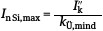
with
| In Si,max | Maximum value of the fuse current rating in A |
|---|---|
| I"k | Prospective short-circuit current (2-pole or 3-pole) in A |
| kÜ,mind | Minimum overcurrent factor |
The rated current for the pre-fused circuit must not exceed this value so that the personal protection afforded by the PPEaA in the specified Arc protection class remains warranted.
Example:
With a prospective short-circuit current of I"k 3 p = 5.472 kA, in order to retain personal protection using PPEaA in the Arc protection class APC 1 with the use of gG-NH fuses, the resulting maximum value for permissible rated current would be
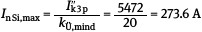
A fuse must be selected with In Si ≤ 273.6 A; it follows that the greatest possible fuse would be NH gG 250 A.
A 7.7
Permissible fuse trip times
On the basis of the prospective short-circuit current under standard exposure conditions and using the characteristic curve factor fKL (refer to Table A 7-2), the permissible fuse trip time tk zul can be determined based on
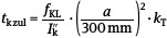
with
| tk zul | Permissible trip time in s |
|---|---|
| fKL | Characteristic curve factor in As |
| I"k | 2-pole or 3-pole short-circuit current in A |
| a | Working distance in mm |
| kT | transmission factor. |
Table A 7-2 Characteristic curve factor for fuse-links
| Characteristic curve factor fKLin As | ||
|---|---|---|
| PPEaA in the Arc protection class | 2-Pole short-circuit | 3-Pole short-circuit |
| APC 1 | 1000 | 500 |
| APC 2 | 2000 | 1000 |
Example:
The precondition of a 2-pole short-circuit with the short-circuit current equalling 5 kA using PPEaA in the Arc protection class APC 1 results in a permissible fuse trip time tk zul = 1000 As/5000 A = 0.2 s = 200 ms.
A fuse should be selected that does not exceed a trip time of 200 ms 2.
Further information regarding the coordination of PPEaA with pre-fused circuits can be found at [22].
The actual flowing electric arc short-circuit currents have smaller values.
For practical applications, a comparison should be made between the permissible trip time and the anticipated trip time of the selected or existing NH fuse. The anticipated trip time should be determined on the basis of the actual fault current (electric arc short-circuit current, not prospective short-circuit current - refer to 4 or Annex 3) from the current-time characteristic provided by the manufacturer for the fuse.