
Abschnitt 4.3 - 4.3 Estimation process for DC installations
4.3.1
General calculation methodology
The assertions that follow apply to low voltage DC installations (LVDC).
Note:
The algorithm applies in particular to direct current circuits, in which a virtual steady-state short-circuit current relationship has set in and/or the short-circuit duration is significantly greater than the DC circuit time constant τ = L/R.
Cases where the time constant is greater and the short-circuit duration is shorter are covered by the calculation base; the results, under certain circumstances, will then encompass safety reserves to a greater degree.
The work environment in DC installations is characterized by the electric parameters
| UNn | Nominal voltage of the DC system (network) |
|---|---|
| RN | Total ohmic resistance of the DC system |
| Pk | Short-circuit power of the DC system (fault location) as well as |
| d | Electrode gap in the DC installation |
| tk | Trip time of the upstream overcurrent protection fuse (short-circuit duration) |
The ohmic resistance of the DC network is comprised of the internal resistance of the DC source (rectifier with an upstream AC network, inverter, battery), the line resistance and the resistance of other elements in the DC circuit (e.g. inductors, etc.).
The short-circuit power in the DC system Pk results from the nominal DC source voltage and the sustained short-circuit current IkDC (stationary value of the short-circuit direct current with a bolted short-circuit at the fault location):
Pk = UNn・IkDC = U2Nn / RN
Note:
The arithmetic mean current value after the transients have subsided is to be considered as the sustained short-circuit current on rectifier-supplied DC systems.
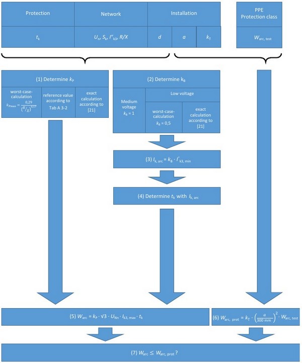
Fig. 4-6
Summary of the estimation process for AC installations
The electric arc short-circuit current Ik, arc, the current limiting factor kB and the electric arc power Parc are determined iteratively by approximating the current-voltage characteristics
Uarc = (34 + 0.532・d)・I0.12k, arc
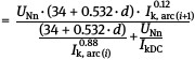
using electrode gap d (the equation applies for the electric arc voltage in V, the electric arc short-circuit current Ik, arc in A and the electrode gap d in mm). The recursion rule applies in general for the iteration (i and i+1 are consecutive iteration steps):
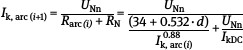
This iteration is undertaken up to a designated abort criterion with specification of an initial value Ik, arc (0).
The following applies for electric arc power
Parc (i+1) = Uarc (i+1) ・ Ik, arc (i+1)
Note:
For expediency, an initial value of Ik, arc (0)= 0,5 IkDCis assumed. The iteration process will be aborted if the results from two consecutive iteration steps fall below a predefined deviation (e.g. 0.5 %).
Normalized arc power can be derived from

The expected value of the electric arc energy is calculated
Warc = Parc・tarc = kP・Pk・tarc
on the basis of the electric arc power or normalized arc power. The arc duration tarc or short-circuit duration tk is determined by the protection settings or protective device characteristic curve analogous to the AC process on the basis of the electric arc short-circuit current Ik, arc.
Note:
When determining the short-circuit duration from the characteristic curves specified by the manufacturer (e.g. circuit protectors), the time constant L/R of the DC system is to be accounted for, if applicable.
The protection level of the PPEaA is determined and evaluated in a manner analogous to the method used for AC installations (Sec. 4.2.3).
4.3.2
Rough estimation based on reference values (worst-case considerations)
For very rough estimations of the electric arc power, the reference value kP max = 0.25 can be used in the DC range:
Parc = kP max・Pk = 0.25・Pk
Application of the iteration process is no longer necessary.
For the low voltage range, one is usually on the safe side with DC systems if a reference value of kB = 0.5 is used for the current limiting factor.