
Abschnitt 4.2 - 4.2 Estimation process for AC installations
4.2.1
Work environment parameters
The working environment in an electrical installation is characterized by the following parameters:
Table 4-1 Work environment parameters
| Work environment | ||||
|---|---|---|---|---|
| Overcurrent protective devices | Electrical network | Electrical system | ||
| tk | UNnR/X | S"k | d | |
4.2.2
Determination of system electric arc energy in the event of a fault
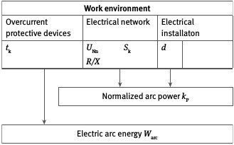
Fig. 4-2
Determination of electric arc energy
The actual electric arc short-circuit current Ik, arc in the low voltage range is significantly lower than the short-circuit current I"k 3 calculated for the installation (a minimal value of the initial 3-pole short-circuit AC current is assumed in this context) due to the limiting characteristics of the electric fault arc. In principle, the applicable correlation is:
| Ik, arc = kB・I"k 3 min | (also refer to A 3.4.2) |
|---|
The current limiting factor kB cannot be precisely determined, but can be ascertained, for example, from a diagram in [21]. Refer to Table 4-2 for reference values.
The limiting properties of the electric fault arc can be disregarded in the > 1 kV range. The following applies: kB = 1.
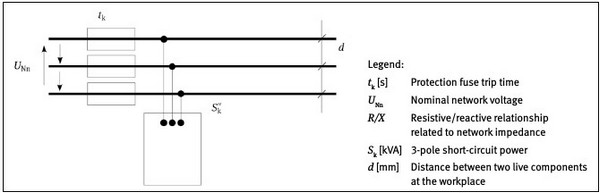
Fig. 4-1
Electrical system parameters
The low voltage range is generally considered to be safe if one assumes a current limitation of 50 % and uses this reduced current to ascertain the trip time from the protection characteristic curve. The current limiting factor then equates to kB = 0.5; it follows that Ik, arc = 0.5・I"k 3,min
The short-circuit duration tk, which is also the arc duration tarc, is now determined using the overcurrent protection characteristics and the electric arc short-circuit current Ik, arc determined (refer also to A 3.4.3).
The trip time is determined using the minimum 3-phase short-circuit current I"k 3,min (worst-case scenario) (refer also to Fig. 4-3).
| With short-circuit durations of longer than 1 s, it can be assumed that the person will be able to withdraw from the immediate danger area, if necessary. For this reason, longer periods will not need to be considered. This does not apply, however, if the person's departure from the work environment is precluded or restricted (e.g. working in tight cable trenches or canals, narrow work corridors, work from ladders or lifting mechanisms). |
|---|
Arc energy Warc is determined by the electric arc power Parc and the arc duration tarc, which corresponds to the short-circuit duration tk up to the trip time of the overcurrent protection device:
Warc = Parc・tarc
Electric arc power Parc is dependent upon the type of arc formation and the geometry of the live components at the fault location. It is determined using the normalized arc power kP from the short-circuit power S"k with the equation Parc = kP · S"k .
Normalized arc power kP can be determined with consideration given to the effective electrode gap d (equipment conductor spacing), e.g. according to the text in German, "Schau, H.; Halinka. A.; Winkler, W.: Elektrische Schutzeinrichtungen in Industrienetzen und -anlagen") [21]. Reference values for kP are specified in Table A 3-2 in Annex 3.
In general, an estimation of arc energy in the event of a fault results in the correlation:
Warc = kp・S"k・tk
Table 4-2 Current limiting factor reference values for a worst-case calculation
| Voltage range | Current limiting factor (reference values) kB |
|---|---|
| Low voltage | 0.5 |
| Medium and high voltage | 1.0 |
With the short-circuit power S"k = √3 ・UNn・I"k 3,max follows Warc = kp ・ √3 ・UNn・I"k 3,max・tk
For worst-case considerations, kP can be replaced by the maximum value kPmax :

The decisive short-circuit current I"k 3 is the prospective 3-pole short-circuit current at the workplace (fault location). This is the result of a short-circuit current calculation (refer to Annex A 3.4.2 and VDE 0102); for this, the maximum value for the 3-pole initial short-circuit AC current must be assumed.
The duration of arc combustion tarc corresponds to the short-circuit duration tk and is determined by the overcurrent protection devices. The short-circuit duration can generally be derived the overcurrent protection device manufacturer's selectivity evaluations and/or trip time characteristic curves (current-time curves).
4.2.3
Determining the PPEaA protection level for the work situation
The protection level Warc, prot afforded by PPEaA is determined by the test level of the PPEaA and the working distance a, as well as the geometry of the installation (factor kT ) (refer to Fig. 4-4).
Working distance a is the distance between the electric fault arc and the operative part of a person's body (torso) while performing work or while present in the working environment under consideration. Where different tasks are being carried out in the working environment, the shortest operative distance should be applied.
It can be assumed that the distance to a person's torso while working will not be lower than a = 300 mm. Different distances may be considered for PPEaA intended for other parts of the body (e.g. head, legs, etc.). Typical values are referenced in Annex A 3.4.5, Table A 3-3.
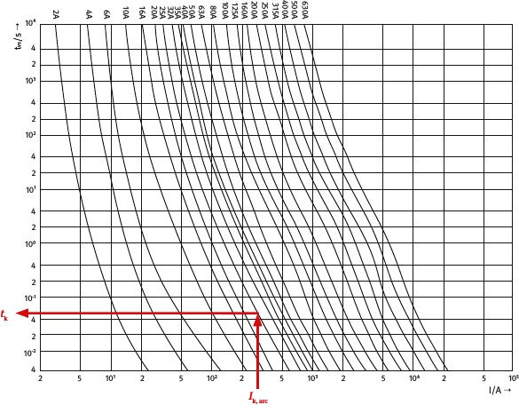
Fig. 4-3
Example for determining the trip time for an overcurrent protection device
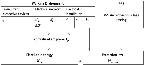
Fig. 4-4
Determination of the protection level
| Protection of the hands is possible only to a limited extent. If the hands are located in the immediate vicinity of an electric fault arc, then an assertion as to the level of protection afforded the hands cannot be made. However, experience gained from actual accidents reveals that, in all cases where burn injuries to the hands have occurred, protective gloves were not worn. Hands are usually drawn away instinctively as a reflex action when a fault occurs. For this reason, protective gloves that have been arc fault tested are recommended. |
|---|
The transmission factor kT considers the electrical system's geometric configuration and describes the spatial propagation of the thermal impact of an electric arc.
In a small-scale installation, the thermal influence of an arc flash propagates directionally. In more open or spacious installations, the thermal influence will propagate in a more omnidirectional pattern (refer to Fig. 4-5).
Exemplary pictures of actual on-site work situations are depicted in Section 6.
The test method used to verify the thermal impact of an electric fault arc is described in detail in Section A 2.2. This test method distinguishes between two Arc protection classes (APC), which define the protection afforded by PPEaA against the thermal effects of electric arcing. Verification for both Arc protection classes is by subjection to electric arcing at the resulting arc energy intensity (test level), using the test setups described in the test method.
| Arc protection class APC 1 | Warc, test_APC 1 = 168 kJ |
|---|---|
| Arc protection class APC 2 | Warc, test_APC 2 = 320 kJ |
Equivalent arc energy Warc, prot can be determined from the electric arc energy of test category Warc, test for any working distance a (≥ 300 mm) using the formula below. It represents the protection level Warc, prot, at which the protection afforded by the PPEaA for the respective distance a is still maintained. 2 Moreover, using the factor kT allows the system configuration to be accounted for.
The following formula applies in general on the basis of the Box test method:

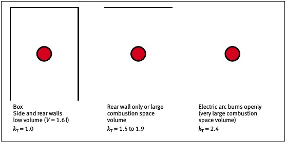
Fig. 4-5
Transmission factor reference values for different installation relationships
Note:
This formula is valid only for the calculation and the selection of PPEaA that has been tested under (IEC 61482-1-2) standardized conditions (a = 300 mm, APC 1 or APC 2).
4.2.4
Selection of PPEaA
Insofar as the expected value of the electric arc energy Warc does not fall below a value of 50 kJ, the relationship to the expected value of the electric arc energy Warc is to be accounted for on the basis of the protection level Warc, prot used for choosing the PPEaA Arc protection class (Box test according to IEC 61482-1-2). The thermal hazards associated with electric fault arching are deemed to have been met if
Warc ≤ Warc, prot applies.
On the basis of this relationship, with application of the determinants and conditional equations referenced above, limitations for the use of PPEaA in a selected Arc protection class can also be determined with respect to
the short-circuit current range,
the permissible short-circuit duration or the trip time of the overcurrent protection device (and with that the overcurrent protection device, itself ),
and the permissible working distance (also refer to Annex 7).
A summary of the estimation process for AC installations is depicted in Fig. 4-6.
Feasibility study in German - "Machbarkeitsuntersuchung zur Prüfung und Bewertung von Schutzhandschuhen gegen thermische Gefahren von Störlichtbögen" (AG: BGFE; AN: STFI/TU Ilmenau), STFI final report from 30 May 2005