
Annex 3 - Parameters and risk analysis of thermal hazards to persons due to electric arcing
A 3.1
General Preliminary remarks
The assertions made in this Annex are tailored for three-phase AC systems. At the same time, the assertions also apply in a figurative sense to DC systems, which will be addressed in the conclusion of the respective section.
A 3.2
Energetic parameters for thermal hazards to persons due to electric arcing
The electrical energy fed into an electric fault arc is almost completely converted therein and emitted or released back in various forms. For this reason, the impact of electric arcing is primarily determined by the electric arc energy Warc. Electric arc energy clearly identifies the relationships associated with system short-circuit-related arcing. Different network and system conditions will result in different electric arc energies.
The significant level of exposure or risk a person is subjected to as a result of thermal influences is the energy density impacting the exposed surface of the skin. This is the incident energy Ei that is present as direct incident energy Ei0 with the thermal impact of a proximate electric arc. If the person is wearing PPEaA, then the incident energy should be considered as transmitted incident energy Eit. In the testing of PPEaA, a determination is made as to whether the transmitted incident energy will exceed the limits for an onset of 2nd degree skin burns (Stoll/Chianta criterion). A successful test will verify that the PPEaA is arc-resistant and provides protection up to the level of direct incident energy as per the test settings.
There is a complicated non-linear correlation between electric arc energy and direct incident energy, which is determined through the specific transmission and exposure relationships, including system configuration and the effective distance between the arc flash and the person (transfer relationship). The transmission and exposure conditions related to thermal influences can be very diverse. A Risk assessment must include or address all related cases and requires a "worst-case" examination.
The correlation between electric arc energy and direct incident energy is known for both Arc protection classes for the Box test of PPEaA (protective textiles and clothing) according to DIN EN 61482-1-2 (VDE 0682-306-1-2) [11]. These are control parameters for the test settings and characterize the transfer relationships for the test setup.
During the Box test, the effects of radiation (including reflections) exist, particularly as a result of arc flash directivity (gas flow) resulting from the small-scale box structure and through "worst-case" transfer conditions influenced by the electrode materials. Comparable examinations with other configurations reveal that, with the same electric arc energy being fed into the Box test structure, the highest level of thermal incident energy results.
A 3.3
Methods for determiningWarcandWarc, prot
The electric arc energy Warc to be expected within the scope of application can be determined using the methods described below. The maximum value of expected electric arc energy will be ascertained and is measured in kJ. Based on this, it must then be verified that the maximum occurring exposure (thermal impact) will not exceed the level of protection and strength afforded by the PPEaA. The related parameter is then the electric arc energy for the test category being examined in the Box test - the test level. The level of equivalent arc energy for the PPE test must meet this level. For specific applications, existing deviations from the distance, geometry and test transmission relationships can be accounted for when determining equivalent arc energy, the protection level Warc, prot.
The relationship to the expected value of electric arc energy must be accounted for on the basis of the test level (equivalent arc energy) when selecting the test category or the Arc protection class of the PPEaA.
The thermal hazards associated with electric fault arching are deemed to have been met if
Warc ≤ Warc, prot applies.
| The test currents for the test categories from the Box test do not correspond with the PPEaA application limits with respect to short-circuit current levels. |
|---|
The risk analysis is comprised of the following work steps:
Determination of the expected electric arc energy value,
Examination of the arc protection level of the PPEaA,
Consideration of divergent exposure conditions.
Comprised in the work steps are the determinations below for the workstation or area being analysed:
Nominal voltage or stipulated network voltage.
Prospective (bolted) short-circuit current (AC: initial short-circuit current or DC: sustained short-circuit current).
The R/X-ratio for the network or the short-circuit electrical circuit impedance (AC) or the ohmic resistance R and the inductance L of the electrical circuit (DC).
Installation geometry (electrode gaps and volume relationships at potential fault locations)
Working distances (potential electric fault arc onset and combustive locations, minimal effective distances to the arc flash).
Type, model, settings and characteristics of the protection device(s) (circuit breakers, fuses or other special protection devices upstream from the work area).
Protection level of the PPEaA test category.
Note:
It should be pointed out that the different switching states of the distribution network or energy supply system can lead to different short-circuit power readings and energy levels. For this reason, it may be necessary to analyse a number of such cases in an installation, and then to investigate the specific case where greatest arc flash hazard exists.
Analysis of the energy supply system must encompass all work areas, which generally comprises the point of supply to the network in question up to the user outlet.
A 3.4
Work steps
Under A 3.4, observations are described for AC and three-phase AC systems that can essentially be applied to DC systems, as well. The particular aspects of DC systems will be addressed in Sections A 3.4.3.1, A 3.4.4.1, A 3.4.6.1 and A 3.4.7.1.
A 3.4.1
Ascertain the general operating conditions
The starting point for the analysis is to consider the general operating conditions. An initial list should be compiled that includes network voltage levels, network equipment types and locations, as well as the work tasks involved.
Note:
It must be kept in mind throughout the process that differing prospective short-circuit current readings can result from the different network switching states and upstream supply systems. Short-circuit current is greatest when the network junction (switchgear bus bar or distributor) is supplied through multiple feed inputs or transformers. Differing short-circuit current values with different switching states in the same system must nevertheless be accounted for, because the electric arc energy at lower short-circuit current levels may definitely be greater than at the higher current levels due to the longer overcurrent protection fuse trip times.
With respect to work activities (electrotechnical work, switching operations), all tasks that are executed on open electrical installations or that call for equipment to be opened (work performed in the vicinity of live components or live working) will play a role.
Note:
In the case of construction-type tested switchgear for which the test validation of arc resistance is available (Medium voltage: Electric arc testing according to DIN EN 62271-200, Low voltage: electric arc testing criterion 1-5 according to EN 61439-2, Supplement 1), personal protection can always be assumed when operating or performing work tasks on a closed system. This does not need to be incorporated into the further analysis. On non-tested systems, it must not be assumed that the system will remain closed in the event of an internal arcing fault and/or that the effects of inadmissible electric arcing will not occur outside the system (e.g. due to escaping hot gases, bursting parts, etc.); this situation must be treated as in the case of an opened system or the hazardous situation must be considered separately.
A 3.4.2
Calculate the short-circuit currents at the work places under study
A prerequisite for the risk analysis and the selection of PPEaA is to be aware of the prospective short-circuit current or short-circuit power associated with the equipment (or network junctions) that will potentially be worked on.
Note:
As a rule, the risk analysis should be undertaken for different workstations in a network or supply system. In larger systems, it is often advisable to develop and observe identical structures and parameters or similar basic electrical configurations (circuits).
The calculation of short-circuit current is to be performed according to the standard methodology described in DIN EN 60909-0 (VDE 0102) [8] or DIN EN 61660-1 (VDE 0102-10) [9]. Calculation software is usually available for this process.
In three-phase AC systems, the maximum and the minimum prospective 3-pole initial
short-circuit AC currents I"k 3,max and
I"k 3,min
are to be determined for each workstation/equipment area for the possible/relevant network switching states. Standard determinations are made of these currents for bolted, zero impedance short-circuits (impedance at the fault location is zero). Information regarding short-circuit currents or short-circuit power can also be obtained through the power supply network operator. It is important to ensure that the short-circuit currents apply to the fault location corresponding to the work location under consideration.
Note:
If only the short-circuit current (or short-circuit power) is provided at the supplying step-down transformer by the low voltage network operator, then the short-circuit current for the work locations (fault locations) remotely located from the transformer in the low voltage network must be calculated from medium voltage to low voltage on the basis of the supply transformer technical specifications, while accounting for the low voltage cable types and lengths used. If applicable, a multi-source feed to the fault location must also be accounted for.
In the event of an actual short-circuit (with arc flashing), reduced current will flow as a result of the electric arcing (fault point impedances) - the electric arc short-circuit current (fault current due to an electric arc short-circuit).
If software is available that can be used for determining the short-circuit current associated with an electric arc short-circuit Ik, arc, then this current should also be determined for the relevant switching states.
Electric arc short-circuit current can be calculated on the basis of I"k 3,min with the help of a current limiting factor kB・ The following applies
Ik, arc = kB・I"k 3,min
Factor kB is determined on the basis of the arc voltage Uarc dependent on the nominal network voltage UNn, the R/X ratio of the short-circuit electrical circuit impedance and the electrode gap d (distance between adjoining conductors in the electrical system).
Note:
The reduction or limitation of the fault current resulting from an electric fault arc at the fault location plays a practical role only in low voltage systems. The current limitations for medium voltage or high voltage networks can be ignored (kB= 1).
A 3.4.2.1
Particular aspects of short-circuit current calculations for DC systems
The prospective short-circuit current IkDC (bolted short-circuit) must be determined in DC systems. The electric arc short-circuit current is determined iteratively.
A 3.4.3
Determine the short-circuit duration (arc duration)
The arc duration tarc or short-circuit duration tk is an essential parameter and will be required for the risk analysis. It is determined by the overcurrent protection device and generally can be taken from the selectivity calculations and/or trip time characteristic curves (current-time curves) provided by the overcurrent protective device manufacturer.
With current-time dependent overcurrent protection fuses, such as a fuse, it must be considered that the trip time will be influenced by the level of the actual short-circuit current and, thereby, from the current limitation through the electric fault arc, itself.
The actual short-circuit current in the low voltage range does not correspond to the prospective short-circuit current, but to the electric arc short-circuit current Ik, arc and can be significantly limited. The actual short-circuit current Ik, arc can only be determined by approximation with consideration given to a number of influencing variables and is subject to a degree of uncertainty (refer to A 3.4.2).
One is generally considered to be in a safe zone if a current limitation of 50 % is assumed and this reduced current is used to establish the trip time, as determined from the current-time curve. Thus, the current limiting factor equates to kB = 0.5; it follows that:
Ik, arc = 0.5・I"k 3,min
When using scatter range information for the current-time characteristic curve for an overcurrent protection device (e.g. fuse), the value from the upper range limit should be used for the short-circuit duration.
Remark 1:
When determining the trip time, the relevant overcurrent protection device from the respective work area should be preferentially used. This can also include overcurrent protection devices that are used or activated on location only during the work time, such as so-called "Safe work fuses". With a multi-source feed to the work area, the overcurrent protection device with the longest trip time should be used to determine short-circuit duration.
Remark 2:
When using software tools (selectivity calculations), it must be ensured that the calculation is made on the basis of the limited electric arc short-circuit current Ik, arc.
Regarding the overcurrent protection devices, their range of protection and selectivity levels must be considered. With non-current-limiting fuses and circuit breakers with direct actuation, the short-circuit duration can be taken directly from the current-time curve or from the temporal selectivity increments (selective tripping schedule). The circuit breaker time delay level or selective trip time settings must also be considered, if applicable. The following reference values are considered to be typical for circuit breaker trip times without a time delay:
Table A 3-1 Typical circuit breaker trip times
| Circuit breaker | Instantaneous trip time |
|---|---|
| Low voltage ( < 1000 V ) | 60 ms |
| Medium voltage ( 1 to 35 kV ) | 100 ms |
| High voltage ( > 35 kV ) | 150 ms |
Related information provided by the manufacturer will provide more precise specifications.
Current limiting fuses feature a short-circuit duration of less than 10 ms. The current-time curves for the fuses exhibit the virtual melting times, meaning the actual trip times will not necessarily coincide. For safety reasons, fuses used in current limiting situations should feature a short-circuit duration tk = 10 ms. This value is considered to be on the safe side.
Note:
At short-circuit durations longer than 1 s, it can be assumed that the person will be able to withdraw from the immediate danger area, if necessary. For this reason, longer periods will not need to be considered. This does not apply, however, if the person’s departure from the work environment is precluded or restricted, such as when working in tight cable trenches or canals, narrow work corridors, or working from ladders or lifting mechanisms.
A 3.4.3.1
Particular aspects of short-circuit duration determinations for DC systems
As a rule, the trip time characteristic curves provided by the fuse manufacturer specify virtual melting times for an electric circuit with a time constant of τ = 0. In practice, for the most part, the extension of the melting time or trip time for τ ≠ 0 can be disregarded because the short-circuit duration is large in comparison to the time constant. Generally, the conversion instructions provided by the fuse manufacturer should be followed. This applies analogous for circuit breakers, as well.
A 3.4.4
Determine the expected value of electric arc energy
The maximum expected value of electric arc energy at the respective fault location or within the work situation being considered is to be determined.
Electric arc energy is dependent on network conditions, meaning from the network short-circuit power Sk at the potential fault location and the short-circuit duration tk, as determined by the electric overcurrent protection devices (trip times for circuit breakers and fuses, as well as separate protection devices if applicable) from the protection characteristic curves:
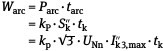
The network short-circuit power at the fault location results from the nominal voltage or the contracted network supply voltage UNn and the maximum prospective 3-pole short-circuit current I"k 3,max for the relevant network switching states.
| With a multi-source feed to the fault location, the short-circuit current I"k 3,max is comprised of the respective partial currents. That portion of short-circuit current from motors that could be fed back to the fault location must be accounted for, if applicable. |
|---|
In general, if a fault occurs within the switchgear or distribution systems, the line impedance between the supply source (usually a transformer) and the system must be accounted for.
Furthermore, electric arc energy is dependent on system conditions characterized by factor kP, which accounts for the type of arc formation and the electrode geometry at the fault location. This factor can be determined by approximation using the electric arc voltage. Empirical conditional equations apply to the electric arc voltage, which - aside from electrical circuit parameters - require knowledge of system conductor wire spacing. The 50 % arc voltage value determination can be assumed [21].
For a very rough estimation without considering the system geometry, the theoretical maxima of the parameter kP can be used, which can be determined using the following equation:

R is the active component thereby, while X is the reactive component of impedance in the short-circuit electrical circuit.
This worst-case calculation should always be used when electrode arrays are aligned directly towards working personnel (see Fig. A 3-1).
Furthermore, it was determined that the following specified range of values kP is typical for conventional system configurations in practice, so that these can be used as reference values (Table A 3-2).
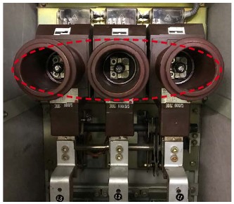
Abb. A 3-1
Electrode array aligned directly towards working personnel
Table A 3-2 Reference values for Normalized arc power
| Nominal network voltage UNn | Distance d | Resistance/Reactance ratio R/X | Normalized arc power kP |
|---|---|---|---|
| 400 V | 30 mm | 0.2 | 0.229 |
| 0.5 | 0.215 | ||
| 1.0 | 0.199 | ||
| ≥ 2.0 | 0.181 | ||
| 45 mm | 0.2 | 0.289 | |
| 0.5 | 0.263 | ||
| 1.0 | 0.240 | ||
| ≥ 2.0 | 0.222 | ||
| 60 mm | 0.2 | 0.338 | |
| 0.5 | 0.299 | ||
| 1.0 | 0.270 | ||
| ≥ 2.0 | 0.253 | ||
| 10 to 20 kV | 120 to 240 | 0.1 | 0.04 to 0,08 |
| Note: When using the maximum value or the reference value, the determination of geometric parameters is circumvented at the cost of precision. A significantly safe distance can emerge under certain circumstances, particularly by applying the maximum value. | |||
A 3.4.4.1
Particular aspects of expected electric arc energy value determinations for DC systems
In contrast to the determination of electric arc energy in AC and three-phase AC systems,
an iterative approach is used for determining the electric arc short-circuit current
and the electric arc power in DC systems, which then is used to determine the arc
energy. The starting point is to identify the current-voltage characteristic of the
DC electric arc using the equation to arrive at an approximation:
Uarc = (34 + 0.532・d)・I0.12k, arc
Note:
In the equation provided, the electric arc short-circuit current is used for A. Using the electrode gap in mm results in the electric arc voltage in V.
This approximation equation is derived from technical measurement analyses and describes the reciprocal current-voltage-correlation associated with the arc flash, for which working points are set for electric arc short-circuiting in the equivalent DC circuit. For simplification, the equivalent circuit is linearized, which considers the arc flash as a linear ohmic resistance Rarc . The following applies for the linearized electric circuit
UNn = Ik, arc・(Rarc + RN).
Resistance RN is the ohmic resistance of the DC system with short-circuited electric arcing and, consequently, is the result of the nominal network voltage UNn and the prospective (bolted) short-circuit current IkDC according to RN = UNn / IkDC.
Using the approach for the electric arc voltage Uarc, the linear arc resistance Rarc = Uarc / Ik, arc is determined, which is subsequently used to determine the electric arc short-circuit current Ik, arc on the basis of the electric circuit equation:
Ik, arc = UNn / (Rarc + RN).
For this, it follows that an iteration process will be necessary.
The value for electric arc short-circuit current is prescribed in the first step in the iteration process. As a matter of convenience, a value of 50 % of the bolted short-circuit current in the electric circuit is used: Ik, arc = 0.5・IkDC. This allows for the electric arc voltage and, subsequently, the associated electric arc resistance to be calculated. With the electric arc resistance, the corrected electric arc short-circuit current can be determined, which then facilitates determination of the electric arc voltage in the next iteration step. The correlated values of electric arc voltage and electric arc short-circuit current in the relevant iteration step i results in the electric arc power for Parc (i) = Uarc (i)・Ik, arc (i). The iteration is complete when a suitable abort criterion has been attained. A deviation of less than 0.5 % can be viewed as being suitable.
For a rough estimation, the electric arc power can also approximate the maximum power to be determined in a viable linear resistance power. For linear DC circuits, this equates to a maximum power at 25 % of the short-circuit power Pk = UNn・ IkDC = U2Nn / RN .
The normalized arc power then equals kp,max = 0.25. Electric arc power is determined according to Parc,max = 0.25・Pk .
Analogous to the AC system, the arc energy is calculated from the resulting electric arc power and the short-circuit duration. Short-circuit duration is determined from the trip time characteristic curves for the overcurrent protection devices using the electric arc short-circuit current.
A 3.4.5
Determine the working distance
Working distance a is the distance between the electric fault arc and the operative part of a person's body (torso) while performing work or while present in the working environment under consideration. Where different tasks are being carried out in the working environment, the shortest distance emerging should be applied. The configuration of the potential electric arc-related electrodes in the system (conductor arrangement) is decisive for determining the fault location (location of the electric arc flash).
Those electrical installations, on which persons perform electrotechnical work on open equipment (repairs, service and maintenance, assembly, inspection, measurement, etc.) are designated as the working environment and workstations. A work task is considered to be any activity performed in the vicinity of live components or live working.
Typical working distances resulting from the person's working posture and the characteristic design or geometry and dimensions of the electrical installation are:
Table A 3-3 Typical working distances
| Equipment type | Typical working distances |
|---|---|
| Low voltage distribution/house junction box, main control cabinet | 300 to 450 mm |
| Low voltage switchgear | 300 to 600 mm |
| Medium voltage switchgear | ≥ 825 mm |
Distance relationships should be determined as accurately as possible in order to establish the working distance. Yet, it can generally be assumed that the distance to the person's torso while working will not fall below a = 300 mm and that this can be applied as a reference value, particularly in the low voltage range.
Note:
Personal protection can always be assumed when working on closed systems that have passed design testing for arc resistance; consequently, a working distance does not need to be determined (refer to Section 3.4.1). In the case of non-tested systems, however, the potential for electric arcing and related effects outside the installation should be anticipated (e.g. when opening doors). The working distance that must then be considered is comprised of the distance to the installation enclosure and the typical working distances referenced above (values taken from the lower limits).
Establishing a safe, minimum working distance to be maintained by a worker represents one potential measure aimed at facilitating work activities using PPEaA at a specific level of protection (test category or Arc protection class).
A 3.4.6
Determine the Arc protection level of the PPEaA
Using a Box test setup according to DIN EN 61482-1-2 (VDE 0682-306-1-2) [11] ensures that the thermal transfer relationships (including output electrode material) will conform to worst-case conditions. Application limits for PPEaA can be taken from the electric arc energies Warc, test in the test settings, which correspond to the respective incident energies Ei0P in the test:
Table A 3-4 Box test parameters
| Box test DIN EN 61482-1-2 (VDE 0682-306-1-2) | Statistical mean value | |
|---|---|---|
| Arc protection class | Electric arc energy Warc, test | Direct incident energy Ei0P |
| APC 1 | 168 kJ | 146 kJ/m2 |
| APC 2 | 320 kJ | 427 kJ/ m2 |
Note:
The specified direct incident energy values Ei0Pthat distinguish the Arc protection classes in the Box test method do not correspond with the ATPV values determined in the tests according to DIN EN 61482-1-1 (VDE 0682-306-1-1) [10] or in the subsequent methods according to NFPA 70E [14] and IEEE 1584 [15]; neither are the underlying transmission or exposure requirements comparable, nor are the analytical conversions or mathematical conveyances possible using these values.
At an operative distance of a = 300 mm (corresponding to the test setup), the electric arc energy values Warc, test lead to the incident energies under consideration. Electric arc energy Warc, test, which identifies the Arc protection class in the Box test, is used as a comparative parameter Warc, prot for the ascertained electric arc energy Warc within the scope of application.
At the same time, it is presupposed that the use of PPEaA is foreseen for working distances of a = 300 mm and for small-scale installations limited by side, rear and partition walls analogous to the Box test setup (with a volume of around V = 1.6・10-3 m3) (refer to Fig. 4-5). Corrections are possible for divergent conditions.
A 3.4.6.1
Arc protection level of the PPEaA for DC systems
For DC applications, as well, the protection level of the PPEaA is determined using the AC test levels from the Box test Warc, test.
Note:
Examinations verified that the energy relationships in DC systems are covered by the applicable requirements for AC systems [28].
A 3.4.7
Consider the divergent exposure relationships
A protection level (equivalent arc energy) Warc, prot, at which protection is still afforded by the PPEaA for the distance a in question, can be determined for any working distance a from the electric arc energy for the test category Warc, test using the experimentally verified reverse squared distance proportionality. Furthermore, the system configuration can also be accounted for. The applicable basic formula for the Box test is
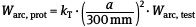
The transmission factor kT for the arc energy for the Box test conditions equates to kT = 1. For divergent firing and transmission conditions, the transmission factor kT can also be set with the following values:
Table A 3-5 Transmission factor kT
| Type of system | Transmission factor kT |
|---|---|
| (Very) small-scale systems with side, rear and partition walls | 1 |
| Large-scale systems, spatial limitations primarily due to rear wall structure | 1.5 to 1.9 |
| Open systems without significant limitations in the electrode chamber | 2.4 |
A 3.4.7.1
Consider the divergent exposure relationships for DC systems
The transmission factor kT from Table A 3-5 can also be used for DC systems. Determination of the protection level of PPEaA also takes place in the same manner as for AC systems using the AC test levels from the Box test Warc, test.
| These examinations verified that the thermal transfer relationships in DC systems are covered by the applicable requirements for AC systems [28]. |
|---|
A 3.4.8
Using the analysis results for the Risk assessment
In the Risk assessment or when selecting the PPEaA test category or Arc protection class (Box test), the relation to the expected value for electric arc energy is to be considered on the basis of the equivalent arc energy. Protection against the Thermal hazards due to electric fault arcing is realized when the electric arc energy Warc is less than or equal to the protection level (equivalent arc energy) Warc, prot.
Warc ≤ Warc, prot
Starting with this relation together with the above mentioned determinant parameters and equations, the limits for PPEaA applicability in a chosen test category or Arc protection class can be determined with respect to the short-circuit current range, permissible short-circuit duration or protection fuse trip time (and therewith the overcurrent protection fuse itself ) and permissible working distance.
A 3.5
Alternative test methods
The procedures described herein are not applicable for alternative test methods to the Box test method. It is then necessary to determine the correlation between electrical energy and direct incident energy (transmission function) generally valid for the test setup in question or to ascertain the direct incident energy that can be expected during individual applications in the event of an accident, and then to compare these with the incident energy level from the PPEaA test.
In addition to the Box test, a test method will be applied in accordance with DIN EN 61482-1-1 (VDE 0682-306-1-1) [10] (Open-Arc test). As opposed to the Box test method, in which a directed test arc is generated similar to a an arc flash that might be expected in an accident when working on a control cabinet or distribution system, the electric fault arc generated in the Open-Arc method is open and non-directional, meaning it is generated in a quasi-open area. The two methods cannot be directly compared and are not transferable or convertible among themselves. On the one hand, this is due to the type of electric fault arc, whose length and propagation are predetermined by the test setup, the electrode materials used and many other physical-technical differences. With the Open-Arc test, the heat transfer that takes place is primarily due to radiation.
On the other hand, the Open-Arc test results lead to the so-called "Arc Thermal Performance Value", or ATPV. Using a statistical methodology in this context, the incident energy is determined, at which level a 50 % probability exists that 2nd degree skin burns will be suffered behind the PPE. Even if an electric arc accident is relatively improbable, the EU regulation related to PPE allows no interpretation of PPE that would tolerate such injury. For this reason, this test method could generally not be used within the EU until July 2019. Only with the 2nd Edition of IEC 61482-1-1: 07-2019 will the prerequisite be established through determination of an additional result parameter ELIM, that the presumption of conformity to the EU regulation can be fulfilled using Open-Arc testing (refer also to A 2.3).
ATPV is the direct incident energy that is generated with the special transfer relations exiting in the test. It should be noted that neither the ATPV nor the ELIM are in accord with the direct incident energy levels associated with the test categories from the Box test. The incident energy levels from the Box test method are neither ATPV or ELIM values nor limits to the range of ATPV or ELIM.
Products available on the international market have been tested under certain circumstances according to both methods, meaning the Box test and the Open-Arc test. Even if the test results are not directly comparable, they can nevertheless help in the selection of suitable PPEaA, particularly when the maximum expected electric arc energy lies above the electric arc energy described in A 3.4.4. for the Arc protection class Warc, test (test level) or the equivalent arc energy Warc, prot (protection level).
For this reason, a manufacturer who tests its products according to both methods can also specify the resulting ELIM for the EU market in order to provide the user with further criterion to facilitate the selection of suitable PPEaA.
When using ATPV and ELIM for selecting PPEaA, however, a risk analysis must be undertaken, in which the expected incident energy is ascertained. Corresponding algorithms are provided for this in NFPA 70E [14] and in IEEE 1584 [15].
Nevertheless, it must be noted that ATPV-based testing and PPEaA selection are bound by the limitations of this methodology.