Abschnitt 6.9 - 6.9 Photo and film flights
Photo and film flights are flights where recordings as images or image sequences are created using image recording equipment.
Additional equipment
Stabilising devices are used to fasten the recording devices on the helicopter. These may require aviation authority approvals.
Flight operation
If the image or image sequence recording can only be made with the door open, the helicopter must be suitable for this (manufacturer's release). Additional persons in the interior are to be provided with assignment-specific Personal Protective Equipment (e.g. ear protection) and communication equipment.
Further measures to minimise hazards can result from the risk assessment.
Annex 1
Information on the execution of risk assessments
General information
The employer or entrepreneur is obliged to take the necessary occupational safety measures according to the German occupational safety and health act and the accident prevention regulation "Principles of Prevention". In doing so, he has to take into account all circumstances that can influence the safety and health of the employees at work. The duty to prepare the risk assessment is a core requirement and applies in all sectors of industry, trade and the service sector. The risk assessment also acquires an increasingly higher importance in other statutory requirements, e.g. in the Ordinance on hazardous substances or the Ordinance on industrial safety and health.
It is thus ensured that the company-specific occupational safety and health protection measures are primarily oriented on the actual hazard situation present in the company. By the preventive approach during the preparation of the risk assessment, the employer not only accomplishes his duty of care towards the employees, but also acquires the possibility of positively influencing the economic situation of the company by reducing accident figures and downtimes.
Operation steps of a risk assessment
The process of preparing a risk assessment includes the identification of all reasonably foreseeable hazards and burdens that can result in connection when carrying out work, the evaluation of these factors (risk assessment), the introduction of measures to minimise hazards and the regular checking of the effectiveness of the measures. Furthermore, documentation on the individual operation steps is to be kept in the company. As the risk assessment is not a static process, regular updates are absolutely essential. A process cycle is created with the goal of organising work as safely as possible.
First step - System delimitation and form of consideration
In order for a sensible and efficient consideration to be carried out, it is to be decided in a company-specific manner, whether a
work place-related,
person-related,
work area-related or
activity-related
risk assessment should be carried out. The classical structure of helicopter companies consists of the sectors administration, maintenance (hangar) and flight operation. For the sectors Administration and Maintenance, the work area-related risk assessment makes sense, for the Flight Operation sector the activity-related risk assessment is relevant.
At the same time, a clear delimitation of the scope of work to be reviewed is to be carried out, in order to define the scope of work of the following steps.
Second step - identifying hazards
A hazard is defined as the possibility of the occurrence of damage or a health impairment. For the identification (recording) of hazards the probability of it occurring or the possible scale of the event is insignificant.
Hazards are thus, for example, characterised by energies and materials coming together with persons in terms of space and time. However, there is also workload stress, or external conditions and requirements that influence the physical and mental state of a person, and must be recognised and taken into account. In practice, plant tours with the OSH Professional and the Occupational Physician, evaluations of accidents, near-misses and illnesses have proven their worth as useful means for recognising the actual situation in the company. The goal of this review is to systematically record all the possible hazards that the insured individuals could be exposed to during their activity.
Checklists can give a first overview here.
| 1. | Mechanical hazards |
|---|---|
| 1.1 | Rotating rotor blade and tail rotor |
| 1.2 | Oscillating loads and Load Lifting Devices |
| 1.3 | Breaking loads and falling parts |
| 1.4 | Lack of sure-footedness/stumbling, slipping |
| 1.5 | Helicopter crash |
| 1.6 | Falling from the helicopter and from work places at heights |
| 1.7 | Moving means of transport |
| 2. | Electrical hazards |
| 2.1 | Defective electrical equipment |
| 2.2 | Electrical overhead power lines |
| 3. | Chemical hazards |
| 3.1 | Handling of fuels and lubricants |
| 3.2 | Handling of plant protection agents |
| 3.3 | Engine and turbine exhaust gases |
| 3.4 | Industrial and fire waste gases |
| 3.5 | Circulating dust |
| 4. | Biological hazards |
| 4.1 | Micro organisms |
| 4.2 | Genetically modified organisms |
| 4.3 | Allergenic and toxic substances from micro-organisms and similar. |
| 5. | Risk of fire and explosion |
| 5.1 | Refueling |
| 5.2 | Handling of explosives |
| 6. | Thermal hazards |
| 6.1 | Contact with hot media |
| 6.2 | Contact with cold media |
| 7. | Physical hazards |
| 7.1 | Noise and vibrations |
| 7.2 | Electrostatic charges |
| 7.3 | Electromagnetic fields |
| 7.4 | Radioactive radiation |
| 7.5 | Downwash |
| 7.6 | Wind gusts |
| 8. | Hazards due to work environment |
| 8.1 | Heat |
| 8.2 | Cold |
| 8.3 | Moisture |
| 8.4 | Dazzling effect |
| 8.5 | Circulating dust and snow |
| 8.6 | Draughts |
| 9. | Physical exposure |
| 9.1 | Moving heavy loads |
| 9.2 | Walking on steep terrain |
| 9.3 | One-sided working posture |
| 9.4 | Stiff physical posture |
| 9.5 | Wearing Personal Protective Equipment (PPE) |
| 10. | Stresses through perceptibility and manageability |
| 10.1 | Manageability of working materials |
| 10.2 | Positioning of control devices and indicators |
| 11. | Psychological distress |
| 11.1 | Excessive demands |
| 11.2 | Stress/time pressure/concentration |
| 11.3 | Short-cycle activity |
| 11.4 | Irregular working hours |
| 11.5 | Constantly changing work places |
| 11.6 | Problems between colleagues |
| 12. | Hazards through poor work organisation |
| 12.1 | Incomplete planning and assignment preparation |
| 12.2 | Incomplete identification of risk factors |
| 12.3 | Lack of knowledge and ability |
| 12.4 | Inappropriate working materials |
| 12.5 | Insufficient inspection obligations |
| 12.6 | Poor communication |
| 12.7 | Incomplete rescue chain |
| 12.8 | Lack of occupational medical prophylaxis |
| 12.9 | Hazard to third parties and by third parties |
Third step - evaluating hazards
In order to be able to select a suitable occupational safety protective measure for the recognised hazards, a risk evaluation is required. Factors for this are the probability of occurrence and the foreseeable extent of damage relating to each individual hazard.
Defining factors for the "probability of damage occurring" are:
duration and frequency of exposure
probability of a hazardous event occurring
possibilities of avoiding or limiting damage.
In the case of the extent of damage a differentiation is made between minor injuries or severe, permanent injuries or the death of a person.
The estimation or evaluation of the existing risk can depend in practice essentially on the personal experience and sensitivities of the evaluating person. In order to objectify this subjective process, for example, it makes sense to use a graphic evaluation procedure. The existing risk is allocated to one of 5 categories using a risk graph (of a decision tree).
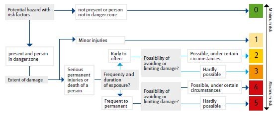
Risks that are evaluated with category 5 represent the greatest possible risk according to the evaluation procedure. In category 0 there is no risk and in category 1 only a slight risk of the probability of damage occurring.
It is defined by the concluding allocation of hazards based on the risk category, whether and to what extent measures to minimise risks or hazards are necessary. In the case of complying with prescribed limit values (e.g. noise), minimum dimensions and distances requirements (e.g. Technical Rules) such an evaluation can be done without.
Fourth step - specify protective measures
All the necessary work safety protective measures are now to be selected and implemented by the employer in accordance with the risk classification. Economic aspects often take precedence in the selection of measures. Expensive technical investments frequently show long-term economic benefits, as the costs for accidents, occupational illnesses and a high level of sickness-related absences must be incorporated in the calculations.
General principles for the selection of suitable protective measures:
The work is to be organised in such a way that a risk for life and health is avoided as far as possible and the remaining risk is kept as low as possible.
The dangers are to be tackled at their source.
The state of the art, occupational medicine and hygiene as well as other substantiated findings of occupational research are to be taken into account in the case of the measures.
The measures are to be planned with the goal of appropriately combining technology, work organisation, other working conditions, social relations and influence of the environment on the work place.
Individual protective measures are to be treated as subordinate, technical measures have priority.
Special dangers for groups of employees in particular need of protection are to be taken into account.
(Selection of measures according to sec.4 German occupational safety and health act)
Technical and collectively effective protective measures are much better accepted by the insured individuals as a rule than, for example, wearing elaborate Personal Protective Equipment. At the same time, technical protective measures are not so easy to consciously or unconsciously circumvent. The increase in occupational safety by organisational or personal measures is much lower compared to technical measures.
Solutions are already pointed out in operational practice for a great variety of hazards e.g. in Technical Rules or in the rulebook of the accident insurance companies. If an employer chooses an individual solution variant, he must at least achieve the same safety level and the same health protection.
Fifth step - check effectiveness, make changes
After introducing the occupational safety and health measures it must be identified whether a minimisation of risks was really achieved in the ongoing work process or if the now existing remaining risk is below the limit risk. The possibility exists that by using the protective measures taken, other already existing hazards are intensified or new hazards are created. In such cases, possibly a more suitable solution has to be found and the process of risk assessment restarted (process cycle). There is no specified time window for reviewing the effectiveness of measures taken. It is up to the employer to stipulate an appropriate period.
The risk assessment is to be updated immediately, if significant changes are introduced to the operating processes or other or new activities are started with own hazards.
These are, in particular:
the procurement of new working materials
change of existing flight and work procedures
handling hazardous goods
the use of or handling of hazardous substances
changes in the field of applicable law
changes in the state of the art
changes in the field of occupational medical prophylaxis
Sixth step - necessary documentation
The employer not only uses the documentation of the risk assessment as a separate work instrument, but it also provides the proof to the state authorities and accident insurance companies that he has accomplished his obligations with regard to the implementation of occupational safety and health protection in the company.
With regard to the form of documentation, the legislator only requires that the result of the risk assessment, the stipulated measures and the result of their review (effectiveness check) are discernible from the documents.
It can comprise documents in the form of electronically saved data or in paper form.
They must include at least:
information on the selected form of consideration
recognised hazards
the assessment of the risk
stipulated occupational safety and health protection measures
concrete dates for the implementation
responsible persons
review of the effectiveness of the measures
date of updating
signature of the employer
Annex 2
Determining of external load forces
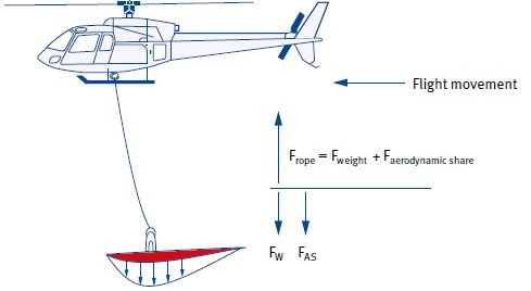
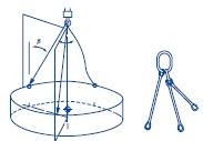
Strongly varying stresses of Load Lifting Devices result from various factors (e.g. oscillating of the load) and flight procedure (e.g. timber logging) in the system of helicopters with external loads. By different accelerations of the helicopter within the scope of aerial work, a dynamic share results in addition to the actual static share of the load. This can briefly assume a 3- to 4-fold value of the static load. The maximum load to be expected results therefore from the static, the dynamic and, in addition, a possible aerodynamic share that can occur based on the negative lift of the load from a specific forward speed. The slinging technology of the load (e.g. tying) also leads to a reduction of the breaking force or carrying capacity of the slinging equipment. Exceeding the carrying capacity or the permanent use of the security area of the Load Lifting Devices can lead to premature wear or to failure. Basis for the dimensioning or the provision of load lifting and slinging equipment by the employer is the reliable determination of the maximum load to be expected.
| Load enlargement by downwash |
|---|
 |
results through the presence of rotor downwash on the surface (red surface) of the load
is of significance up to approx. 30 km/h forward speed, after this value, not relevant
depends greatly on the geometry of the load (e.g. convex or concave surface form)
can be determined by trials in various suspension heights for various helicopter types
Load enlarging factor downwash LD
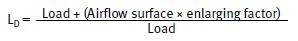
Example: In the case of an airflow surface of 6 m2 and an enlargement of 40 kg/m2 (AS 332c Super Puma, suspension height 20 m, load 1000 kg) results in an enlarging factor of 1.24 (increase of 24 percent).
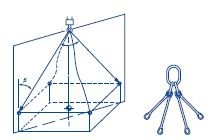
| Load enlargement by Forward Speed Drag |
|---|
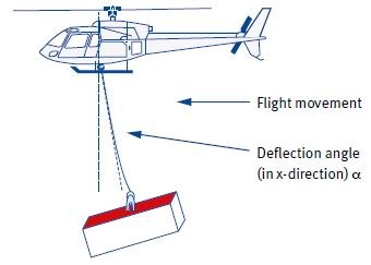 |
results through deflection of the load (e.g. through air resistance or through inertia force)
is calculated through angular relationships (ratio between weight force and deflection)
plays a subordinate role in the case of normal geometry of the load
is reduced by the reduction of speed
Load enlarging factor Forward Speed Drag LF
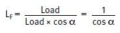
Example: In the case of a deflection of α = 30° in x-direction results due to the angular relationships in a factor of 1.15.
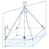
| Load enlargement through Bank Angle |
|---|
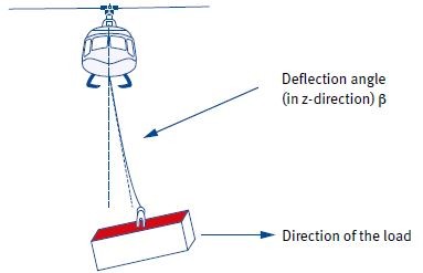 |
results by deflection of the load (e.g. through centrifugal force in curves or air resistance)
is calculated through angular relationships (ratio between weight force and deflection)
depends on the curve speed
is determined by the curve radius
Load enlarging factor Bank Angle LB
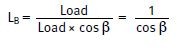
Example: In the case of a deflection of ß = 40° in z-direction results due to the angular relationships in a factor of 1.3.
| Load enlargement through acceleration of the load |
|---|
 |
results through accelerations of the load (e.g. starting load multiple or interception of the helicopter with load)
is calculated e.g. through inertia law
Load enlarging factor accelerations LA
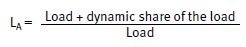
Example: is covered in practice by the so-called "static limit load factor" according to CS-27/29.865.
| Load enlargement by aerodynamic component |
|---|
 |
results through aerodynamic forces on the load (air flow of the load)
differs greatly depending on the model and version of the load and can only be determined for the individual case
has as the consequence that the load must be slung at the pressure point
Load enlarging factor aerodynamic components LAS
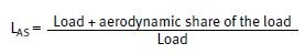
Example: The factor for the aerodynamic share e.g. of an aircraft as external load (in inverted flight position) can in the case of a forward speed of 70 km/h be 1.8.
Summary of the factors
The factor of load enlargement is composed of the multiplication of the individual components. It covers the quasi-static stresses by swaying/bank angle and the dynamic stresses (blows) by acceleration peaks. The factor for "Working flight without logging" (Helicopter External Sling Load Operation, HESLO 1, 2, 4 and 5) is 3.0 and for the type of work "Logging" (Helicopter External Sling Load Operation, HESLO 3) based on higher acceleration peaks 3.5.
Special constructions for load lifting require a precise calculation by the manufacturer taking all expected factors into consideration.
Annex 3
Attaching of external loads
The Load Lifting Devices (chains, steel and textile ropes, round slings, connection links etc.) available on the market are, as a rule, not dimensioned and coordinated with the special requirements of underload flight operation. Findings that, for example, accelerations occurring in flight operation in the helicopter and external load system can induce significantly higher forces than in the quasi-static crane operation or that the upsurge behaviour of ropes represents a major hazard to the crew, are not or not sufficiently taken into consideration when designing the constructions. It is the employer's task to make suitable Load Lifting Devices (LLD) for the work task available to the employees.
The selection and procurement of Load Lifting Devices for flight operation can be made in different ways:
A separate dimensioning and selection is carried out for a specific load case and for each deployed Load Lifting Devices. This method makes sense for special loads or when procuring load-related LLD.
LLD for the general load case (daily working routine) are dimensioned for the maximum expected loads and taking all possible load increasing factors into consideration.
In operational practice the provision of assortments according to weight classes of helicopters (max. external load carrying capacity of the helicopter according to manual) has proved useful for economic and safety reasons. The wrong selection of LLD is minimised by separate storage and targeted use.
At the same time, requirements of the manufacturers of helicopters or cargo hooks are to be observed. It is frequently not possible, for example, to attach multi-leg slings to the primary cargo hook so that intermediate rings (e.g. oval rings) have to be inserted.
The LLD dimensioned and designed for the general load case can be used taking the specific requirements of flight operation into consideration.
Force-fit and form-fit
In the helicopter sector it corresponds to the rule of technology that loads are attached with positive fit and positive connection. In this way, it is prevented that a load can slip out of the slinging device during the flight by oscillating, rotating or tilting.
The slinging types "wrapped" or "coiled around" are not suitable for helicopter transport. The slinging types "tied" and "double tied" fulfil the requirement according to form-fit and force-fit.
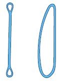
| Force-fit and form-fit during slinging | ||
|---|---|---|
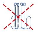 | 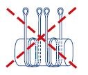 |  |
| wrapped | coiled around | double tied |
|---|
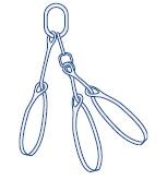
Multiple leg slinging
In the helicopter sector it is generally the technical rule that multiple leg suspension gears are slung with a suspension link (e.g. oval ring) in a hook. The slinging of 3 or more round slings in one hook is to be avoided.
When using one- or two-leg slinging devices, these are to be dimensioned in such a way that one leg can safely lift the load plus load increasing factors.
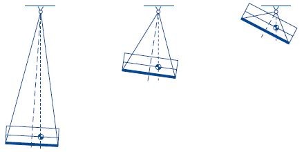
| Multiple leg slinging |
|---|
 |
The load attached with four-leg suspension gear, whereby only two legs are load-bearing during
In the case of three- or four-leg suspension gear, a maximum of two carrying legs can be counted on. The reason for this is the dynamics in the flight operation. It is to be assumed that the load does not hang exactly symmetrically, stably and without swinging or turning with the load centre of gravity directly under the load rope.
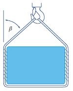
Angle of inclination of the slinging devices
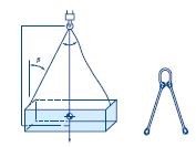
In the helicopter sector it is generally the technical rule that the angle of inclination to vertical does not exceed 45°. In the case of an angle of inclination of 60° the complete weight force has the effect in two-leg suspension gear in each leg and the possibility exists that the slinging devices on the loads are drawn together.
| Angle of inclination of the slinging devices |
|---|
 |
Dimensioning of cargo hooks
In the helicopter sector it is generally the technical rule that adequately dimensioned cargo hooks, in relationship to the dimensions of the slinging devices, even two legs, can be directly suspended in the hook. The cargo hook must be able to safely lift the load plus load increasing factors (e.g. angle of inclination and swinging of the load). In doing so, the maximum angle of inclination to the vertical angle of 45° and for example the non-overlapping of the lifting belts in the hook must at all costs be complied with.
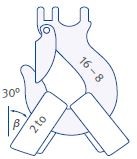
| Cargo hooks with round slings | ||
|---|---|---|
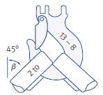 | 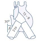 | 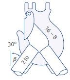 |
| cargo hook dimension 13 - 8 (WLL 5.4 to) in relation to load (>1 to) over-dimensioned, but: | ||
| wrap 45° round slings 2 to = hook not optimal to critical overlap | 30° round slings 2 to = better, but round slings | 30° round slings 2 to, hook dimensions 16-8 = round slings optimally placed |
(to corresponds to tonne)
| Cargo hook with lifting belt | ||
|---|---|---|
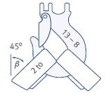 | 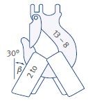 |  |
| cargo hook dimension 13 - 8 (WLL 5.4 to) in relation to load (>1 to) over-dimensioned, but: | ||
| 45° lifting belt 2 to = hook position not optimal to critical overlap | 30° lifting belt 2 to = better, but lifting belts overlap | 30° lifting belt 2 to, hook dimensions 16-8 = lifting belt optimally placed |
(to corresponds to tonne)
The maximum carrying capacity is significantly reduced by bent edges or lifting belts that are inserted and overlapped. The transmission of the force in the hook by the lifting belts must take place if possible at the bottom of the hook.
| Force transmission at the bottom of the hook | ||
|---|---|---|
 |  |  |
Length of load lifting and slinging equipment
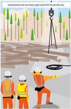
The safe transport of an external load on the helicopter is mainly determined by the sufficient length of the load lifting and slinging equipment. Hazards for the Marshallers on the ground, the crew and for the environment can be minimised by a sufficient distance of the load from the helicopter or of the helicopter from the ground or structural installations.
The length of the actual load rope must therefore be selected in such a way that the helicopter can hover over the highest obstacle with a clearance reserve of 5 m in the event of forced setting down of the load in case the load touches the ground.
In the case of multiple-leg suspension gear the angle of inclination of the legs and therefore the burden of slinging devices and slinging points is reduced with increasing attaching length. The handling of the load by the Marshallers is also facilitated, as the distance to the pivot point of the load is enlarged.
| Length of load lifting and slinging equipment |
|---|
 |
The impacts of downwash on the load or the surroundings also decrease at the same time with increasing distance. A load that is attached with too short a rope further restricts the pilot's possible courses of action, e.g. in the case of a stall.
As the maximum values of downwash result at a distance of approx. 1.5 times the rotor diameter, loads are not to be positioned there.
Load increasing factors by slinging (selection)
| Type of slinging "Direct" | Load of LLD | |
|---|---|---|
 | Load | 100 % |
| Load increase | 0 | |
| Load increasing factor | 1.0 | |
| Overall load | 100 % | |
| Number of legs or units with sufficient carrying capacity | 1 | |
| Number of load-bearing legs or units | 1 | |
| Load per leg | 100 % | |
| Type of slinging "Tying" | ||
 | Load | 100 % |
| Load increase | 20 % | |
| Load increasing factor | 1.2 | |
| Overall load | 120 % | |
| Number of legs or units with sufficient carrying capacity | 1 | |
| Number of load-bearing legs or units | 1 | |
| Load per leg | 120 % | |
| Type of slinging +"Tying + angle of Inclination" | ||
 | Load | 100 % |
| Load increase | 20 % | |
| Load increasing factor | 1.2 | |
| Overall load | 120 % | |
| Number of legs or units with sufficient carrying capacity | 2 | |
| Number of load-bearing legs or units | 1 | |
| assuming that the entire load is carried by one leg | ||
| Load per leg | 120 % | |
| Type of slinging "2-leg suspension gear (TWLS)" | Load of LLD | |
|---|---|---|
 | Load | 100 % |
| Load increase | 0 | |
| Load increasing factor | 1.0 | |
| Overall load | 100 % | |
| Number of legs or units with sufficient carrying capacity | 2 | |
| Number of load-bearing legs or units | 1 | |
| assuming that the entire load is carried by one leg | ||
| Load per leg | 100 % | |
| Type of slinging "3-leg suspension gear (THLS)" | ||
 | Load | 100 % |
| Load increase | 41% | |
| Load increasing factor | 1.41 | |
| Overall load | 141 % | |
| Number of legs or units with sufficient carrying capacity | 3 | |
| Number of load-bearing legs or units | 2 | |
| assuming that the entire load is carried by two legs | ||
| Load per leg | 70.5 % | |
| Type of slinging "4-leg suspension gear (FLS)" | ||
 | Load | 100 % |
| Load increase | 41% | |
| Load increasing factor | 1.41 | |
| Overall load | 141 % | |
| Number of legs or units with sufficient carrying capacity | 4 | |
| Number of load-bearing legs or units | 2 | |
| assuming that the entire load is carried by two legs | Load per leg | 70.5 % |
| Type of slinging "3-leg suspension gear (THLS) + ties" | Load of LLD | |
|---|---|---|
 | Load | 100 % |
| Load increase | 70% | |
| Load increasing factor | 1.7 | |
| Overall load | 170 % | |
| Number of legs or units with sufficient carrying capacity | 3 | |
| Number of load-bearing legs or units | 2 | |
| assuming that the entire load is carried by two legs | ||
| Load per leg | 85 % | |
Load increasing factors by slinging (summary)
| Cause | Load increasing factor | Explanation |
|---|---|---|
| Straight lift | 1.0 | applies for angle of inclination in the range 0°-10° |
| Angle of inclination to vertical | 1.41 | applies for angle of inclination up to 45 ° |
| Tying of slinging equipments | 1.2 | does not apply in case of sharp edges and too small radius |
Load increasing factors through flight behaviour
"Helicopter External Sling Load Operation" (HESLO 1, 2, 4 and 5)
| Cause | Load increasing factor | Explanation |
|---|---|---|
| Forces by flight procedure (e.g. banking, accelerations) | 2.5 | static limit load factor |
| Supplement for sudden jolted accelerations | 1.2 | based on different measurements |
| Summary | 3.0 |
"Helicopter External Sling Load Operation" (HESLO 3) Logging
| Cause | Load increasing factor | Explanation |
|---|---|---|
| Forces by flight procedure (e.g. banking, accelerations) | 2.5 | static limit load factor |
| Supplement for sudden jolted accelerations | 1.4 | based on different measurements |
| Summary | 3.5 |
The factors listed here only illustrate the load increasing factors based on dynamic influences and reflect the current state of the art.
Summary load increasing factors for Load Lifting Devices
| "Helicopter External Sling Load Operation" (HESLO 1, 2, 4 and 5), working flight without Logging | "Helicopter External Sling Load Operation" (HESLO 3), Logging | ||||||
|---|---|---|---|---|---|---|---|
| Load increase by | Material | LLD | SE | 3-/4-leg suspension gear | LLD | SE | |
| Flight procedure | Steel textile | 3.0 | 3.0 | 3.0 | 3.0 | 3.5 | 3.5 |
| Slinging techniques | Steel textile | 1.2 | 1.41 | 1.7 | 1.2 | ||
| Material strengths | Steel textile | 1.80 2.62 | 1.80 2.62 | 1.80 2.62 | 1.80 2.62 | 1.80 2.62 | 1.80 2.62 |
| Product | |||||||
| Individual calculation | Steel textile | 5.40 7.86 | 6.48 9.43 | 7.61 11.08 | 9.18 13.36 | 6.30 9.17 | 7.56 11.00 |
| General use | Steel textile | 6.48 9.43 | 9.18 13.36 | 7.56 11.00 | |||
Explanations:
Helicopter External Sling Load Operation (HESLO 3), Logging: A higher strain on LLD results from the work procedure by load peaks than in normal external load flights. These peaks are induced during the load pick-up or load drop-off as a rule. A combination with "bank angle" is therefore not probable.
Flight procedure: Covered by the static limit load factor (according to CS-27/29.865) up to the value of 2.5.
Slinging equipment SE (round slings, chains) is, as a rule, tied and loaded with angle of inclination. As each leg must carry the entire load, it is only calculated with the slinging technique factor "straight lift with tying". 3- and 4-leg suspension gear is often used in combination with the slinging techniques "tying" and "angle of inclination". The factor 13.36 is to be applied here for general use for safety reasons.
Material strengths (material, processing and environmental factors): Depending on the material selection (e.g. textile: polyamide, polyester etc.), special ageing behaviour or type of manufacturing (e.g. pressing or splicing) further additional factors are necessary here.
General use: The LLD provided for the general load case and for the maximum carrying capacity of the helicopter covers every load case in the case of complying with all parameters (also flight operation).
Individual calculation: A calculation for the respective individual case is possible taking all load increasing factors into consideration.
The LLD dimensioned for general lifting gear operation are designed according to Annex I of the Directive 2006/42/EC (Machinery Directive) in the case of metal parts normally with a working coefficient of 4, in the case of wire ropes and their end connections normally with a working coefficient of 5 and in the case of textile fibre ropes or belts normally with a coefficient of 7. In order to determine to what extent these LLDs are suitable for the helicopter assignment with regard to their work load limit, a comparative study is necessary taking into account the working coefficient and the actually existing load increasing factors.
Comparative study step 1
Stipulation of maximum external load work load limit of the helicopter according to the manufacturer's specifications.
Comparative study step 2
Stipulation of the maximum load of Load Lifting Devices or a component taking into account the load increasing factors (e.g. flight procedure, materials used, slinging technique).
Comparative study step 3
Stipulation of the breaking strength of the LLD or component to be assessed.
Comparative study step 4
Study of the breaking strength of the LLD in relation to the maximum load of the LLD.
Comparative study step 5
Assessment of the suitability of the LLD or of a component with regard to the work load limit during the helicopter external load assignment.
Application example (steel cable):
| Work step | Explanation |
|---|---|
| Step 1 Maximum external load carrying capacity of the helicopter WLL (Heli) 1400 kg | These details can be found in the documents of the helicopter's manufacturer. As a rule the manufacturer indicates the maximum external load carrying capacity as WLL (Working Load Limit). |
| Step 2 Maximum load of LLD LOAD (max.) 9072 kg | This value results from the multiplication of the maximum external load carrying capacity of the helicopter with the corresponding load increasing factors (HESLO 1, 2, 4 and 5, general assignment, steel rope as Load Lifting Devices: value 6.48) 1400 kg x 6.48 |
| Step 3 Breaking strength of LLD BS (LLD) 12500 kg | This value results from the multiplication of the maximum load carrying capacity of
the LLD to be assessed (also labelled with WLL directly on the LLD) with the working
coefficient for the general lifting gear operation according to the Machinery Directive
(see manufacturers' specifications). WLL (steel rope) 2500 kg Working coefficient 5 2500 kg x 5 |
| Step 4 Breaking strength of LLD BS (LLD) 12500 kg Maximum load of LLD LOAD (max.) 9072 kg | BS (LLD) 12500 kg > LOAD (max.) 9072 kg |
| Step 5 The steel rope is to be considered as suitable for the external load assignment with regard to carrying capacity. | Assessment of the suitability of the Load Lifting Devices (here steel rope, WLL 2500 kg) on a helicopter with a maximum external load carrying capacity of 1400 kg. |
Example of use (round sling):
| Work step | Explanation |
|---|---|
| Step 1 Maximum external load carrying capacity of the helicopter WLL (Heli) 1400 kg | These details can be found in the documents of the helicopter's manufacturer. As a rule the manufacturer indicates the maximum external load carrying capacity as WLL (Working Load Limit). |
| Step 2 Maximum load of LLD LOAD (max.) 13202 kg | This value results from the multiplication of the maximum external load carrying capacity of the helicopter with the corresponding load increasing factors (HESLO 1, 2, 4 and 5, general assignment, round sling as slinging equipment: value 9.43). 1400 kg × 9.43 |
| Step 3 Breaking strength of LLD BS (LLD) 14000 kg | This value results from the multiplication of the maximum load carrying capacity of
the LLD to be assessed (also labelled with WLL directly on the LLD) with the working
coefficient for the general lifting gear operation according to the Machinery Directive
(see manufacturers' specifications). WLL (round sling) 2000 kg Working coefficient 7 2000 kg × 7 |
| Step 4 Breaking strength of LLD BS (LLD) 14000 kg Maximum load of LLD LOAD (max.) 13202 kg | BS (LLD) 14000 kg > LOAD (max.) 13202 kg |
| Step 5 The round sling slinging device is to be considered as suitable for the external load assignment with regard to carrying capacity. | Assessment of the suitability of the Load Lifting Devices (here round sling, WLL 2000 kg) on a helicopter with a maximum external load carrying capacity of 1400 kg. |
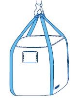
| Examples of slinging external loads | |
|---|---|
| FIBC (Big Bag) for helicopter transport | Information: Select hook size so that all 4 loops with a free leg length of 1 m can be places next to each other at the bottom of the hook. In the case of shorter legs the lift must be carried out, for example, with four-leg suspension gear, to guarantee an angle of inclination < 45°. It makes sense to indicate the slinging techniques on additional pictograms directly on the FIBC. |
 | |
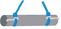
| Examples of slinging external loads | |
|---|---|
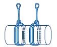
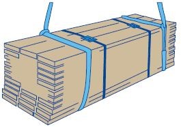
| Pile of planks with several loose piles standing next to each other | Information: Sawn planks tied with lashing straps to a "load unit". A round sling attached respectively right and left with coiling around (form-fit and force-fit). Slinging technique can only be used in the case of additional secured piles (load units). Due to the possibility of the load being able to twist there is a tendency to rotate or see-saw. Edge protectors prevent damage to round slings. |
 | |
| Examples of slinging external loads | |
|---|---|
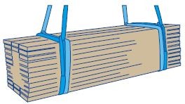
| Pile of planks with several loose piles standing next to each other | Information: Sawn planks without further lashing straps attached respectively on the right and left with two round slings and coiling around as a stable load (form-fit and force-fit). Slinging only with equal length round slings possible. Edge protectors prevent damage to round slings. |
 | |
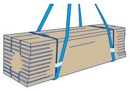
| Pile of planks with several loose piles standing next to each other | Information: Sawn planks tied with lashing straps to a"load unit". A lifting belt wrapped on the right and the left respectively and secured against slipping (stable load). This slinging technique is only possible in the case of additional secured piles (load units). Edge protectors prevent damage to lifting belts and lashing straps. Lashing and slinging equipment can be used as one unit. |
 | |
| Examples of slinging external loads | |
|---|---|
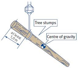
| Logs of wood | Information: The slinging point must be selected at least 1 m from the front and at the thicker end of the log. The centre of gravity may not be chosen as attachment point, as the log can tend to twist and rotate during the flight. |
 | |
| Pipes with a smooth surface | Information: The possibility exists, when attaching such pipes or materials, that the slinging device shifts to the centre during the flight and the load therefore becomes unstable. An additional fixing measure is therefore necessary. In order to reach a defined flight position in the case of forward speed, the use of special air deflectors (e.g. brake parachute) is possible on the external load. |
 | |
| Inappropriate Load Lifting Devices and slinging techniques | |
|---|---|
| Clamping and vacuum lifters | no form-fit and force-fit |
| Spreaders for bore holes and hollow parts | no form-fit and force-fit, in the event of a momentary unloading the load can be lost |
| Forks (crane forks) | no form-fit and force-fit |
| Hooks without safety catch | no form-fit and force-fit |
| No low-torque ropes as Load Lifting Devices | rotate under load |
| Belts, shapeless webs with loose covers | flying up in flight operation, vibrating and banging |
| Constructions with sharp, narrow thimbles | tips can bend, danger of getting caught |
| Rope cast heads | too massive (too big), connection is hard to secure |
| Eddy rotational hooks as swivels on load ropes | are not made for permanent load |
| Eddy rotational hooks without ball bearings as slinging equipment | rotate when not under load |
| Multiple leg suspension gear without corresponding ring or slinging equipment divided by cargo hooks | position of the legs not clear, load destabilised, suspension in primary cargo hook not possible safely, slinging equipment can slip through |
| Steel rope without thimbles | steel loops can twist, damage of the rope to be expected |
| Textile ropes without thimbles | damage of the rope by friction in a very short time |
| Type of slinging wrapped or coiled around | no form-fit and force-fit |
| Tying with loose strands | round slings can be destroyed, for example, by friction heat during tightening, |
| Slipping of slinging devices over each other | destruction possible by friction heat |
Annex 4
Instructions and briefings
Instructions
In order to ensure the safety and health of the employees during all activities in the company, and if possible to improve these, employees must be regularly instructed in safety. As well as this legal obligation, there are however further reasons that make regular and comprehensible training sessions necessary.
These are, among others:
Instructions help to avoid accidents and therefore to avert suffering for the employees involved and unnecessary costs for the company.
The employees recognise that the employer cares about safety at work.
A trouble-free work procedure is made possible.
The goal of instructions is to ensure safe work. This is not possible without knowledge of the risks and necessary safety measures. The necessary knowledge, capabilities and also wishes do not result by themselves, it has to be conveyed.
When must employees be instructed?
initial instruction before starting the activity or in case of taking on a new task, comprehensive instruction on all occurring hazards, burdens and their averting
regular repetitions at least once a year
depending on the type and extent of hazards and burdens more frequently than yearly
after specific incidents and serious accidents
in case of specific activities (e.g. assignment in noise sectors)
when handling hazardous substances
in case of ascertained unfavourable safety or health behaviour
Who must instruct?
The employer or other superiors from the company are obliged to do so. If necessary, further persons (e.g. Heads of Operations) can be involved.
Basically, there is also the possibility of using electronic media as tools within the scope of instructions. It should be observed here that the instruction contents are made available individually and specifically for each work place. The possibility must exist at all times that the insured individual can contact an instructing person. A comprehension test should take place after completion of the instruction with electronic tools.
Planning and execution of the instruction:
set instruction goals (selection of topics)
compile information material (e.g. training cards)
stipulate the duration of the training (max. one hour)
specify the size of the group (max. 8 persons in case of practical exercises)
stipulate the time window (the attentiveness of participants is higher in the morning than in the afternoon)
select the location of the event (possibly also directly at the work place)
observe the state of knowledge of all participants (demands not too high or too low)
stipulate training date and announce it in good time
involve participants (active participation, questions and discussions)
carry out practical exercises (inform and instruct)
summarise contents of the training
prepare documentation
check the success of the training
Briefings
There are always several persons at different locations taking part in assignments with helicopters. It is important to ensure that all participants not only know their work task but are also informed about the whole procedure of the assignment. At the same time, assignment-specific safety options are indispensable, so that it is possible to act safely and in a coordinated manner in critical situations. A briefing before the assignment is therefore imperative.
Contents of the briefing
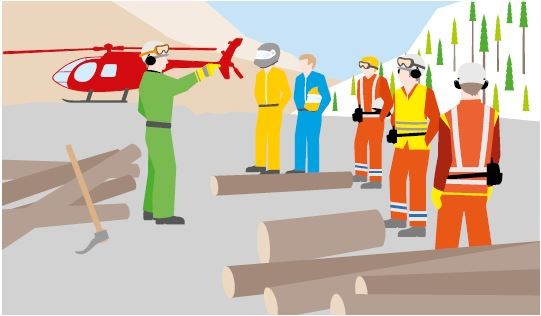
The briefing is carried out immediately before the assignment starts. It should be carried out basically by the Head of Operations or helicopter pilot with the participation of an experienced Marshaller.
The briefing does not constitute the actual education or work training of the employees. This must already take place at a much earlier stage in the company.
It should:
give orientation and an overview of the present work task and situation (circumstances, conditions and particularities)
give information on the concrete work execution (spatial configuration and procedure)
enable coordination of the various procedures (among others at the load pick-up point and load drop-off point)
serve to issue clear directions
serve to remind about already agreed fundamental safety measures and rules of conduct
enable special, necessary arrangements for the individual assignment
Topic selection for the operational briefing using the example of "wood logging"
What does the assignment contain?
amount of wood and type of wood, assortment
possible weights of the merchandise to be transported
state of the wood and degree of dryness
____________________________________________
Where is the assignment flown/completed?
outside working station: approach, landing spot, refueling place, type of refueling, available working materials, car parking situation, material, Load Lifting Devices and slinging equipments, retreat area for third parties, emergency landing places, danger signals, traffic and access regulations
load pick-up site: position of logging, environmental conditions, possible accesses for persons, danger zones, start of work and work direction, approach direction, take-off direction, security area for Marshallers, site for emergency jettisoning
load drop-off site: approach direction, load drop-off site and direction, security area for Marshallers, turning area, slinging equipment depot
flight path: flight obstacles, alternative routes, risks for/due to the surroundings, necessary safety measures
____________________________________________
Who flies the command?
participants: names and phone numbers, positions, tasks, competences, duties, who does what and how, group formation, collaboration with external companies, coordination of work
____________________________________________
How is the order carried out?
work organisation, concrete work procedure, load collectives, slinging techniques, number of rotations, fuel stops, breaks, catering, communication, radio communication, commands, hand signals
____________________________________________
When is the order carried out?
expected duration, planned start and finish of the order, timing, rotation times, weather development
____________________________________________
Special measures during implementation?
accident risks, special safety measures, Personal Protective Equipment, behaviour around the helicopter, tidiness, work discipline, radio discipline, emergencies, first aid measures, first aid workers, first aid material
____________________________________________
After the assignment - debriefing
An important component of the flight or order follow-up is the debriefing. Debriefing can take up a significant share of the time in the case of complex assignments.
Both positive and negative findings as well as procedures during the completed assignment should be discussed and evaluated here. The goal is to make safe procedures reproducible and to analyse problems, uncertainties and hazards that have occurred. After recognising the causes, suggestions for improvement and measures to increase safety for the following orders must be stipulated (risk assessment principle).
Annex 5
Means of communication
Communication is "part of safety" during all operations with helicopters. For this reason, the standardisation of signs, words and instructions and the sensible use of technical aids are of great safety importance.
Handling radio equipment
The radio device or combination of radio device and protective helmet with intercom form the basis of verbal communication during the helicopter assignment. Each employee taking part must be able to operate a radio device to transmit exclusively necessary and important messages to those taking part in the assignment. It is imperative that a functional check is carried out before the respective assignment, for the employee is responsible for the operational readiness of the radio device following the takeover.
It must:
be treated carefully
be used in suitable protective sleeves
be used in vertical position, as the power output of the antenna is lowest in direct extension of the antenna
be used in special carrying bags and secured against falling out
be protected against strong vibrations and blows
be protected against intensive contact with water, snow and moisture
be kept ready for use, i.e. the batteries or the radio devices are to be recharged with special chargers after the end of the activities
be ensured that defective devices are replaced
Commands via radio must be unambiguous, in chronological order and spoken clearly and distinctly. It should be spoken into in a normal tone of voice, not too loud.
| Command | Meaning |
|---|---|
| Down | Helicopter descends |
| Up | Helicopter climbs |
| Altitude 3, 2, 1 | Indication of position in metres, e.g. distance load-ground |
| Hold | Helicopter maintains height and position |
| Right/left | Helicopter hovers to the right/left from the pilot's point of view |
| Proceed forward/back | Helicopter hovers forward/back from the pilot's point of view |
| Direction 11 o'clock | Helicopter hovers towards indicated direction from the pilot's point of view |
| Contact | Marshaller seizes lifting hook at shoulder level/load touches ground |
| Attached | Slinging device is attached to the hook |
| Rope tightened | Load Lifting Device/load rope tightened/under load |
| Detached | Slinging device is detached from the cargo hook |
| Disconnected | Slinging device is disconnected from the load |
| Clear | No obstacles in flight path |
| Stop stop | Break off of current operation, awaiting further instructions |
The listed commands are to be used for general transport and assemblies. They represent a selection taken from practical experience and can be adapted to the internal company needs in the enterprise.
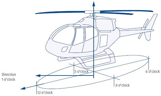
Flight direction details are given in metres and in the order of sequence: "Flight direction - distance in metres" clockwise from the pilot's point of view.
| Command | Meaning |
|---|---|
| 1 | Distance indications in metres |
| Up/down 1 | Direction indication with distance |
| Direction 1 o'clock 10 | Direction indication with distance with shift by clock-reference direction |
| Clock-reference direction from the pilot's point of view |
|---|
 |
In order to call a helicopter or a station directly, for example, the internationally valid ICAO radio alphabet is used.
| A | ALFA | (ælfa) | I | INDIA | (indi.ɑ) |
|---|---|---|---|---|---|
| B | BRAVO | (braːˈvo) | J | JULIET | (dʒuːli.ˈet) |
| C | CHARLIE | (tʃɑːli) | K | KILO | (kiːlo) |
| D | DELTA | (deltɑ) | L | LIMA | (liːmɑ) |
| E | ECHO | (eko) | M | MIKE | (mɑik) |
| F | FOXTROT | (fɔkstrɔt) | N | NOVEMBER | (noˈvembə) |
| G | GOLF | (ɡʌlf) | O | OSCAR | (ɔskɑ) |
| H | HOTEL | (hoːˈtel) | P | PAPA | (pəˈpɑ) |
| Q | QUEBEC | (keˈbek) | V | VICTOR | (viktɑ) |
| R | ROMEO | (roːmi.o) | W | WHISKEY | (wiski) |
| S | SIERRA | (siˈerɑ) | X | X-RAY | (eksˈrei) |
| T | TANGO | (tænɡo) | Y | YANKEE | (jænki) |
| U | UNIFORM | (juːnifɔːm) | Z | ZULU | (zuːluː) |
| 1 | ONE | (wən) | 6 | SIX | (siks) |
|---|---|---|---|---|---|
| 2 | TWO | (tu:) | 7 | SEVEN | (se-vən) |
| 3 | THREE | (thrē) | 8 | EIGHT | (āt) |
| 4 | FOUR | (fȯr) | 9 | NINE | (nin) |
| 5 | FIVE | (fiv) | 0 | ZERO | (zir-(ˌ)ō) |
International ICAO spelling table with phonetic reproduction
Example for calling a helicopter:
D-HEGF "Delta-Hotel Echo Golf Foxtrot" usually: "Golf Foxtrot"
Example for calling out numbers:
| 20 | "Two Zero" | 85 | "Eight Five" |
|---|
All figures are transmitted by articulating all individual figures, whole hundreds or thousands in generally common pronunciation.
The employer shall endeavour to ensure that special working radio devices can be used for HESLO, induced by disturbances on the aircraft radio by third parties.
Marshalling helicopters by hand signs
Marshalling a helicopter means that the pilot is marshalled by a suitable person on the ground with clear hand movements that must be defined and known beforehand.
Marshalling is necessary if there is not sufficient space for safe solo landing or the pilot cannot safely estimate the lateral distances to the surrounding setting.
A very uneven landing ground can also make it necessary.
Rules for marshalling helicopters:
If possible, establish radio communication with the pilot or the crew.
Marshalling is carried out from the helicopter's point of view against the wind, i.e. the Marshaller must have the wind behind him and face the landing area.
Visual contact with the helicopter and later eye contact with the pilot is to be established.
The landing site is to continue to be observed during the landing process.
It is imperative that the Marshaller maintains his position during the landing process even in the case of strong downwash or driving snow.
If necessary, a kneeling position is to be assumed.
In case of critical situations or in cases of doubt, the landing should be forgone or the manoeuvre aborted.
When necessary, instructions to fly off must be given.
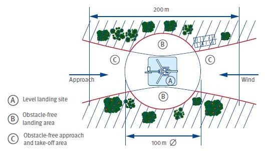
Optimum loading site conditions are present, if the direct landing site is level and has a square surface with an edge length of 12 to 20 m, depending on the size of the helicopter. The obstacle-free landing area should thereby have a diameter of 100 metres.
Points to assess the landing site:
clarification of real estate (consent)
existing flight obstacles (buildings, trees, masts, overhead power lines, ropes, poles and fences)
necessary protection of the surroundings (structural installations traffic routes and natural vegetation)
level landing site (necessary size)
terrain as level as possible, flat direct landing site without hollows
stability of the ground at the direct landing site (e.g. snow)
possibilities of stirring up loose ground (not natural ground, sand and gravel)
necessity of moistening the ground to avoid dust development
space for main and tail rotor
presence of loose objects (boards, tarpaulins, sheets of metal, equipment, belts or vegetation)
possibility of access and traffic regulations
animals in the surroundings, even within fences and stables
possible wind directions and wind speeds
| Landing site design |
|---|
 |
Selection of signs for marshalling the helicopter
| Meaning | Description | Illustration |
|---|---|---|
| Attention At beginning Use caution | Hold up right arm. Palm of the hand faces forward |  |
| Stop Interruption Do not continue to execute movement | Extend both arms sideways vertically, palms of the hands face forward |  |
| Stop - Danger | Extend both arms sideways horizontally, palms of the hands face forward and bend and extend arms alternately |  |
| Lift Up | Hold up right arm, palm of the hand faces forward and makes slow, circular movement |  |
| Sink Down | Hold down right arm, palm of the hand faces inward and makes slow, circular movement |  |
| Slowly | Extend right arm horizontally, palm of hand faces down and is moved up and down slowly |  |
| Taking off | Keep right arm up, palm of the hand faces forward and move arm sideways to and from |  |
| Come forward | Bend both arms, palm of the hand faces inwards and beckon with the underarm |  |
| Go back | Bend both arms, palm of the hand faces outwards and beckon off with the underarm |  |
Annex 6
Information on setting up outside working stations
1 General information
The employer must take all the necessary measures to set up suitable outside working stations according to the type of use and the spatial possibilities. Coordination measures for spatial division, timing and maintenance of all safety measures are to be regulated in good time and comprehensively. Using the example of the type of operation "wood logging" basic requirements are illustrated below.
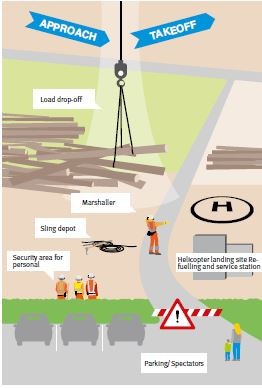
2 Outside working station
Necessary spatial division for the safe operation of an outside working station:
load drop-off site
sufficiently stable road for vehicles
approach area, turning area, take-off area for the helicopter
security zone for ground personnel in case of danger
area for storing necessary slinging equipments
helicopter landing site with refueling and service station
fuel storage area
if present, workshop and store for air traffic material
parking area for vehicles
stopover zone for uninvolved third parties
General safety rules:
In the spatially divided areas (e.g. load pick-up or drop-off site) only those persons are to stay that are immediately involved in the transport process.
Third parties must stay outside the necessary barriers in a safe area or room.
If necessary, safety lookouts are to be deployed to actively enforce the safety measures.
Objects, external loads to be lifted or loose vegetation that could be stirred up by the rotor downwash, must be secured or removed.
Vehicles are only to be parked on allocated parking spaces.
Open fires or open flames are to be forbidden.
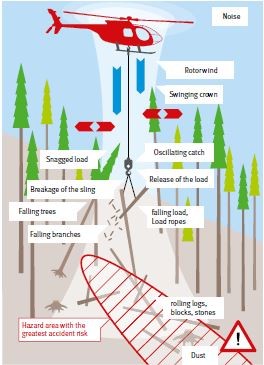
2.1 Outside working station - conduct at the load pick-up site
The process of load lifting can become necessary in extremely difficult terrain. This includes, in particular, steep terrain, slippery ground, stony places and all types of obstacles. But further hazards such as noise or the stirring up of dust become effective even during the actual activity. This working environment requires unconditional compliance with rules of conduct.
General rules of conduct:
constantly record hazards that arise from the working environment (terrain, ground cover, tree population, falling objects) and coordinate behaviour accordingly
wear Personal Protective Equipment/conspicuous working clothes
actively keep third parties away
Before the approach of the helicopter:
identify, think through and determine the work procedure before the helicopter approaches
identify and stipulate security area and escape routes depending on the approach to be expected
take a firm and safe standing point
complete preparatory work, in particular, the attaching of slings to the load
During helicopter approach:
direct gaze in the direction of the helicopter or the canopy of standing trees
above all, observe and safely grasp cargo hooks and empty slings that are in the cargo hook
pay attention to falling branches or stirred up objects
let the cargo hook moving at great speed touch down on the ground first and then grasp securely
After attaching the load:
Go to the security area immediately, never stay underneath the load.
Always move to safety diagonally to the slope or uphill - never downhill. The retraction path or escape path must be in the opposite direction to the load movement and the take-off direction of the helicopter.
All persons must go to the same security area and may not leave in different directions.
Hoisting the load and flying off:
The command to lift the load may only be given, if nobody can be endangered by the hoisting of the load.
The danger zone and the load are to be observed from lifting the load to flying off. Attention should be paid especially to falling objects (branches, crown pieces, trees falling over, load parts).
In particular, attention must be paid to the intended and proper fit of the slings.
If necessary, a clear command to stop the hoist is to be given.
Work may only be continued, if flying off has taken place.
2.2 Outside working station - conduct at the load drop-off site
The same rules of conduct apply for the load drop-off site as for the load pick-up site.
Prerequisite for safe work is a sufficiently large and appropriate storage area. In this way, it is avoided that unnecessarily high or confusing flight polders arise. If necessary, several load drop-off sites are to be stipulated.
In order to ensure eye contact between the pilot and the Marshaller on the ground, the security area and the storage area of the slinging equipments should be laid out on the pilot side of the helicopter. The escape route to the security area must always be kept clear.