
Annex 5 - Examples
The following examples depict work being carried out at different work locations in a typical municipal low voltage supply system.
Note:
The following examples were compiled from the viewpoint of the experts who have collaborated on this DGUV Information. The examples are provided in support of those who apply this selection guide. Individual evaluations undertaken in operational practice may account for local conditions or specific work processes that bring about different results.
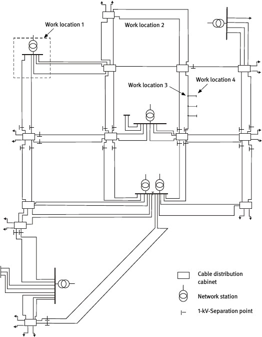
Fig. A 5-1
Municipal low voltage supply system being considered
A 5.1
Example 5.1: Low voltage distribution in a transformer station (Work location 1)
Work tasks are frequently carried out on low voltage distribution systems at transformer stations. Examples might be the removal or replacement of NH fuse-links, connection and disconnection of output circuitry, measurement and testing of active components or cleaning tasks.

Fig. A 5-2
Working on a low voltage distribution system
Risk assessment of the planned activities
Phase 1: Is there a principle danger of exposure to persons due to electric arcing?
Yes
Work tasks are performed that require physical contact with open live installation, on which electric arcing can occur.
Phase 2: Initial evaluation of electric arc energy associated with the scope of activity or workplace. Is a calculation required?
Yes
When working on low voltage installations, PPEaA can be dispensed with in the following situations:
When working on measuring, control and regulation equipment with upstream electric circuit protection up to 25 A.
→ not applicable
When working on electrical circuitry with rated voltages up to 400 V with upstream protection up to and including 63 A, insofar as an outfit of customary work clothing comprised of long-sleeved outer clothing and long pants is worn.
→ not applicable
When working on electrical circuitry with rated voltages up to 400 V AC and a short-circuit current < 1 kA. (such an electric arc will burn unstably and extinguish immediately.)
→ not applicable
An increased degree of risk exists when performing the work in question because, in the event of a fault at the workplace, significant short-circuit power is generated directly behind the transformer. The transformer output, as well as the transformer fuses or power supply branch circuit breaker trip times are decisive for the energy released into an arc flash. One important factor is influenced by the structure or the switching status of the low voltage network with relationship to the type of energy supply to the low voltage stations (station meshing or per station low voltage network supply). The short-circuit power and the prospective short-circuit current at the workplace depend on whether a unilateral or a multilateral supply exists.
Phase 3: Apply the calculation methodology: Determine Warc, Warc, prot!
Step 1: Data for the workplace being considered
This example deals with a municipal supply system (Fig. A 5-3), in which Work location 1 will be considered. There are 20/0.4 kV transformers present at the network stations with rated capacities SrT of 630 kVA or 400 kVA and short-circuit voltages uk of 4 %. The standard 1-kV aluminium cable cross-sections are 150 mm2 for the network cables and 35 mm2 for the house installation cables.
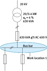
Fig. A 5-3
Equivalent circuit at Work location 1
The drawing in Fig. 5-1 depicts the network separation points, which can be opened during work on live components in order to establish a unilateral energy supply to the respective network areas in question. Work location 1 is supplied by a 630 kVA transformer over a 630 kVA NH transformer fuse with operating class gTr AC 400 V. The fuse current-time curve is depicted in Fig. 5-4.
Step 2: Determination of I"k 3, R/X
The results from the short-circuit current calculation according to VDE 0102 [7] for the unilateral energy supply switching status at the work location yield a prospective short-circuit current (initial short-circuit alternating current) I"k 3 of
| I"k 3,max = 24.5 kA | (c = 1.05) |
|---|---|
| I"k 3,min = 21.6 kA | (c = 0.95) |
The R/X ratio for network impedance in the fault circuit equates to approximately 0.27.
Step 3: Determination of Electric arc current
The minimum fault current relevant for the NH fuse trip time with an electric arc short-circuit current results from the minimum prospective short-circuit current I"k 3,min using the limiting factor kB, which characterizes the current-limiting effects of the electric arc in the fault circuit. Because a low voltage system and a worst-case examination are being dealt with in the initial approach, a current limiting factor of kB = 0.5 will be assumed according to Section 4.2.2. For minimum fault current, it follows that
Ik, arc = kB・I"k 3,min = 0.5・21.6 kA = 10.8 kA
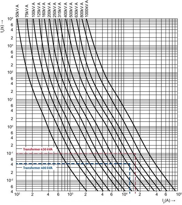
Fig. A 5-4
Mean time/current characteristic curves for the gTr AC 400V fuse in use
The trip time for this current as derived from the fuse characteristics in Fig. A 5-4 is t = 0.113 s. This time equates to the short-circuit duration tk.
Note:
In practice, the characteristic curve for the actual overcurrent protection device in use should be applied.
Step 4: Electric arc power at the workplace
Using the maximum prospective short-circuit current I"k 3,max , it follows for short-circuit power at the workplace that
S"k = √3 ・UNn ・I"k3,max = √3 ・400 V・24.5 kA = 16.97 MVA
Under worst-case conditions, the maximum possible value for normalized arc power can be determined using the formula. For this example, the computation yields
kP,max = 0.36.
From this, the electric arc energy Warc results:
Warc= kP・S"k ・tk = 0.36・16.974 MVA・0.113 s = 690.3 kJ
This energy is the expected value for electric arc energy at workplace 1 in the event of a fault.
Step 5: Establish the working distance
The working distance for work on low voltage distribution systems is set at a = 300 mm. This corresponds to the minimum distance between a person's torso and the frontal area of the opened equipment.
Step 6: Test level for the PPE
The test levels for PPE under standardized Box test conditions according to VDE 0682-306-1-2 are
Arc protection class APC 1: Warc, test_APC 1 = 168 kJ
Arc protection class APC 2: Warc, test_APC 2 = 320 kJ
Step 7: Transmission factor, PPEaA protection level
When working on low voltage distribution systems in transformer stations, it should be assumed that large-scale installations will be used with spatial limitations primarily due to a rear wall structure. A transmission factor of kT = 1.5 is assumed at this location. Using a working distance of a = 300 mm, it follows for equivalent arc energy that

Warc, prot_APC 1 = 252 kJ with Arc protection class APC 1
Warc, prot_APC 2 = 480 kJ with Arc protection class APC 2
Step 8: Selection of Arc protection class
Warc = 690.3 kJ > Warc, prot_APC 2 = 480 kJ applies.
The expected electric arc energy is greater than the protection level Warc, prot_APC 2 of PPEaA in the Arc protection class APC 2. In this case, proceed with the Risk assessment in Phase 4.
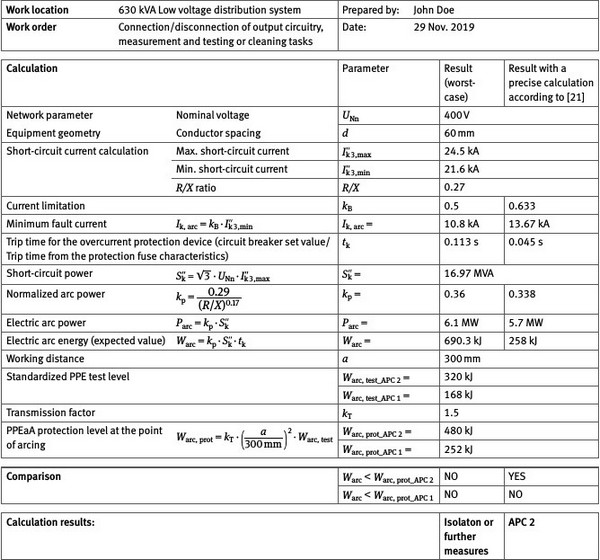
Execution of the required work steps will yield the results below (refer to Table A 5-1).
Phase 4: Implement further measures towards reducing electric arc energy and the probability of injury due to electric fault arcing.
Suitable measures for reducing arc energy and the probability of injury due to electric fault arcing are not possible for the installation and the work situation in question. Therefore, proceed with Phase 5.
Table A 5-1 Results of the calculations for Warc and Warc, prot for Example 5.1 (630 kVA transformer station)
Phase 5: Estimate the probability of occurrence and the severity of injury due to electric fault arcing after the adopted measures have been implemented. Evaluate the residual risk and make a decision (Risk matrix)
In this phase, the potential severity of damage (severity of injury) and the probability of injury due to electric fault arcing are estimated in order that residual risk can be determined.
Estimation of the severity of injury
It is assumed in this example that the calculation (according to Section 4) for the working conditions being considered will yield the following results:
| Protection level for PPEaA APC 2: | Warc, prot | = 480 kJ (kT = 1.5; a = 30 cm) |
|---|---|---|
| Arc energy: | Warc = 690.3 kJ | |
The relationship Warc / Warc, prot = 1.44 results in an anticipated severity of injury designated as "Reversible injury" according to Table A 4-1.
Estimation of the probability of injury
Table A 5-2 Estimation of the probability of injury for 5.1
| Designation | Evaluation points | Explanation | |
|---|---|---|---|
| a) | Type/condition of equipment | 4 ... Unlikely | Open construction in a self-contained electrical operating facility. An evaluation of condition through visual inspection shows the installation in a properly maintained and clean state |
| b) | Technical measures | 2 ... Conceivable, but very unlikely | The use of bypass-resistant equipment (live working tools; voltage tester, NH fuse handle with sleeve) |
| c) | Organizational measures | 2 ... Conceivable, but very unlikely | Description of the organizational measures Application of operational rules: Work and operating instructions are available Qualification of personnel: The deployment of qualified personnel for these tasks (qualified electricians) |
| d) | Personal measures | 2 ... Conceivable, but very unlikely | The use of PPEaA in the Arc protection class APC 2, the use of NH fuse handle with sleeve |
| e) | Statistical influencing factors | 4 ... Unlikely | Limited space in critical areas: well-arranged structural design; critical areas are clearly identifiable Frequency and duration of work activities in areas where PPEaA protection in the Arc protection class APC 2 is not available: limited to removal of NH fuse-links - short work duration Possible additional protective effectiveness through the use of long-sleeved, flame-resistant undergarments: no Findings from statistically sound and comparable electric arc incidents in the past: Knowledge known about electric arc incidents |
| f ) | Ergonomic influencing factors | 2 ... Conceivable, but very unlikely | Experiences gained within the company through the use of different PPEaA or tools: PPEaA and the tools for working on live components were selected together with the participation of affected personnel |
| Summation: | 16 falls in the range (10 to 19) | Result: The anticipated probability of injury due to electric arcing can be termed "Conceivable, but very unlikely" |

Fig. A 5-5
Application of the Risk matrix for Example 5.1
A Risk assessment yielding a Severity of injury Warc / Warc, prot = 1.3 "Reversible injury" and the Probability of occurrence at 16 points "Conceivable, but very unlikely" places the results in the green section of the Risk matrix (Fig. A 5-5). It is therefore permissible to perform the work tasks with PPEaA in the Arc protection class APC 2 on the basis of the evaluation approaches adopted.
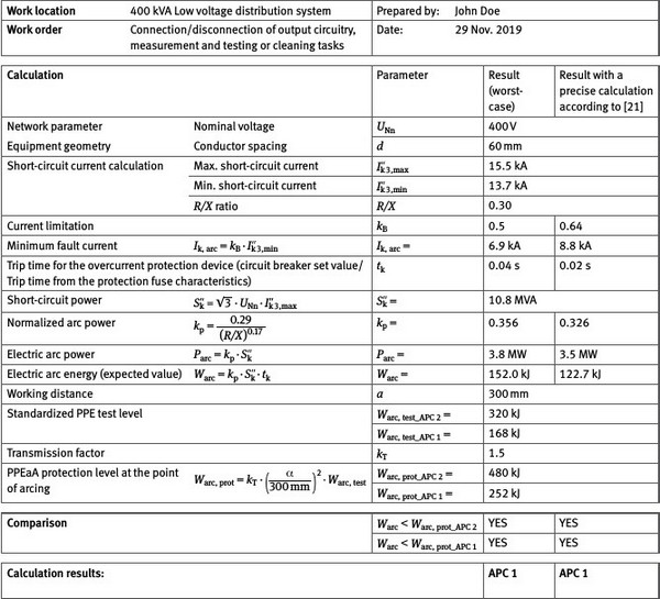
In the case of a station with a 400 kVA transformer (short-circuit voltage 4 %; NH fuse 400 kVA gTr AC 400 V), the prospective short-circuit current - under otherwise similar conditions as above - will fall within the range I"k 3 = 12.7 to 14.1 kA.
The R/X ratio equals 0.27. A current-time curve for the NH fuse (Fig. A 5-4) for kB = 0.5 and Ik, arc = 6.9 kA results in a short-circuit duration of tk = 0.04 s. The short-circuit power equals S"k = 10.8 MVA. A normalized arc power of kP = 0.356 results in an electric arc power of Parc = 3.8 MW and an expected value of electric arc energy at Warc = 152 kJ. The same working distance a = 300 mm and the same transmission relationship (kT = 1.5) means that PPEaA in the Arc protection class APC 1 will be required.
Refer to Table A 5-3 for the results of the calculation.
Table A 5-3 Results of the calculations for Warc and Warc, prot for Example 5.1 (400 kVA transformer station)
A 5.2
Example 5.2: Low voltage cable (Work location 2)
Work is frequently carried out on cable sleeves in the cable network (refer to Fig. A 5-6). Work location 2 in this example (cable sleeve after approx. 100 m network cable) as depicted in Fig. 5-1. The level of fault current and electric arc energy is greatly dependent on the distance between the work location and the network supply station (transformer) and, for this reason, on the length of the corresponding network cable.

Fig. A 5-6
Working on a cable sleeve
In this example, the work location is being fed through a network cable from a 630 kVA transformer station. The NH fuse in the supplying station's cable branch is decisive for breaking the electric fault arc. In this context, an NH 250 A full-range line fuse is used with operating class gG or gL AC 400 V. The current-time curve is depicted in Fig. A 5-7.
Risk Assessment
Phase 1: Is there a principle danger of exposure to persons due to electric arcing?
Yes
Work tasks are performed that require physical contact with live conductors, on which electric arcing can occur.
Phase 2: Base evaluation of the electric arc hazard for the work task or the working environment. Is a calculation required?
Yes
None of the requirements listed in Section 1, in which the use of PPEaA can been dispensed with, have been fulfilled.
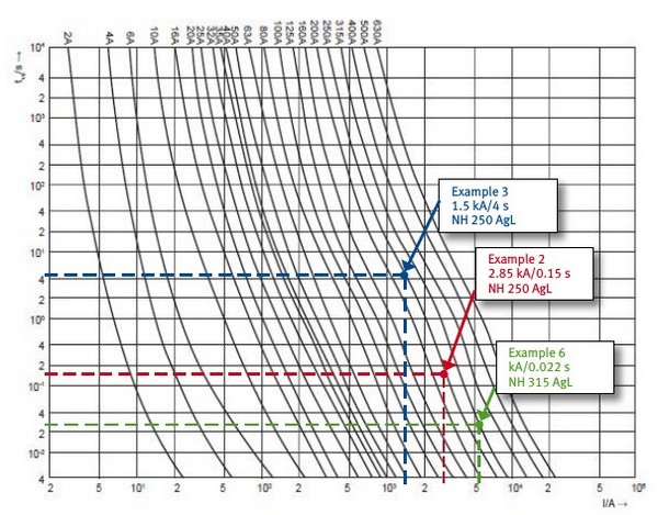
Fig. A 5-7
Mean time/current characteristic curves for the NH gL/gG AC 400 V line protection fuse being considered
Phase 3: Apply the calculation procedure: Determine Warc, Warc, prot!
Execution of the required work steps will yield the results below.
Table A 5-4 Results of the calculations for Warc and Warc, prot for Example 5.2 (cable network sleeves)
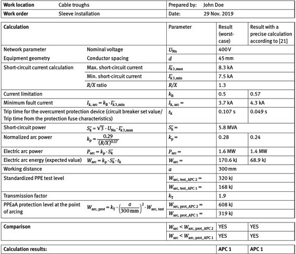
The work under consideration at Work location 2 (cable sleeves) according to the estimation in Section 3 and with the precise calculation requires PPEaA in the Arc protection class APC 1.
A 5.3
Example 5.3: House junction box (Work location 3)
The replacement of a house junction box is often associated with work on live equipment (Fig. A 5-8; inside/outside). Such an example in Work location 3 is considered in Fig. A 5-1. Energy is once again supplied to the work location from an upstream network station with a 630 kVA transformer. In contrast to Example 2, the short-circuit current is significantly less because the house connection cables have only comparatively small cross-sections. The house connection cable in the example has a length of approx. 15 m.
The branch fuse in the upstream cable distribution cabinet is decisive for a short-circuit shutdown; in this case, an NH 250 A fuse is used with operating class gG AC 400 V.

Fig. A 5-8
Working on a house junction box
Risk assessment of the planned activities
Phase 1: Is there a principle danger of exposure to persons due to electric arcing?
Yes.
Work tasks are performed that require physical contact with open live installation, on which electric arcing can be initiated.
Phase 2: Initial evaluation of electric arc energy associated with the scope of activity or workplace. Is a calculation required?
Yes.
None of the requirements listed in Section 1, in which the use of PPEaA can been dispensed with, have been fulfilled.
Phase 3: Apply the calculation methodology: Determine Warc, Warc, prot!
Execution of the required work steps will yield the results below (refer to Table A 5-5).
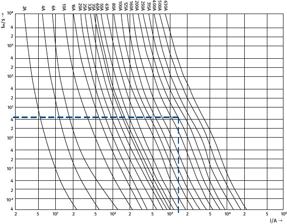
Fig. A 5-9
Mean time/current characteristic curves for the NH gL/gG AC 400V line protection fuse
being considered
Table A 5-5 Results of the calculations for Warc und Warc, prot for Example 5.3 (open house junction box)
Phase 4: Implement further measures towards reducing electric arc energy and the probability of injury due to electric fault arcing.
It can be seen from the results in the example that PPEaA in the Arc protection class APC 2 is not adequate for work on a house junction box. The high expected value of electric arc energy is brought about by a long short-circuit duration, which results in a long period of exposure.
In order to facilitate work in this case, for example,
overcurrent protection devices guaranteeing defined and sufficiently rapid shutdown characteristics must be used or
compliance with an adequate minimum distance must be required or
PPEaA must be tested for greater levels of incident energy
The option mentioned first will be singled out for consideration below. For this, it must be ensured that the NH 250 A gG branch fuse present in the network supply station's cable branch is replaced with a safe-work fuse with a low rated current and/or with fast-acting or super-fast-acting operating characteristics for the duration of the work task. This means that, prior to beginning and subsequent to completing the work task, a fuse replacement will be necessary. If an NH 160 A safe-work fuse is used with an operating class aR (fast-acting: üf2; very-fast-acting: üf1; super-fast-acting: üf01; hyper-fast-acting: üf02), a current-limiting shutdown will result in any event. Regarding the calculations in this context, a short-circuit duration of tk = 0.01 s is to be applied. An NH 160 A aR/690V - üf01 fuse is used for this example, whereby a trip time of 6.87 ms results.
Table A 5-6 Results of the calculations for Warc and Warc, prot for Example 5.3 when using an safe-work fuse (open house junction box)
The calculation reveals that the expected arc energy is less than 50 kJ. Therefore, specific PPEaA is not required for the work task under consideration. An outfit of customary work clothing comprised of long-sleeved outer clothing and long pants is sufficient. When installing the safe-work fuse, however, bear in mind that the use of PPEaA (APC 1 or APC 2) will be required.
A 5.4
Example 5.4: Electrical installation behind the house junction box (Work location
4)
When work is performed on live components or in the vicinity of live components in an electrical household installation (400 V), which is fuse-protected with a maximum rated current of 63 A, an outfit of customary work clothing comprised of long-sleeved outer clothing and long pants is sufficient (refer to Scope of application).
Note:
For the sake of completeness, the example specified here is taken from the 1st Edition of this DGUV Information (issued October 2012). Calculations from the 1st Edition reveal that the estimated values for Warcare significantly below (factor >27) the protection level afforded by PPEaA in the Arc protection class APC 1.

Fig. A 5-10
Working behind the house supply system
Risk assessment of the planned activities
Phase 1: Is there a principle danger of exposure to persons due to electric arcing?
Yes
An electric arc incident can occur when working on distribution systems, such as when replacing a live electricity meter.
Phase 2: Initial evaluation of electric arc energy associated with the scope of activity or workplace. Is a calculation required?
No
When working on low voltage installations, PPEaA can be dispensed with in the following situations:
When working on measuring, control and regulation equipment with upstream electric circuit protection up to 25 A.
→ not applicable
When working on electrical circuitry with nominal voltages up to 400 V with upstream protection up to 63 A, insofar as an outfit of customary work clothing comprised of long-sleeved outer clothing and long pants is worn.
→ applicable
When working on electrical circuitry with rated voltages up to 400 V AC and a short-circuit current < 1 kA. (such an electric arc will burn unstably and extinguish immediately.)
→ not applicable
A 5.5
Example 5.5: Removal of NH fuse-links
A meter installer's field of work can encompass work areas associated with different electric arc hazards:
- a)
Working on equipment (meter) behind the house service fuse (compare the example for Work location 4):
These activities comprise tasks, such as checking voltage and replacing meters (in a voltage-free or a live state). Depending on the computed results, PPEaA in the Arc protection class APC 1 is sufficient for this.
- b)
Work on an opened house junction box; (compare the example for Work location 3):
When preparing for working on a meter, the service fuse must be removed or reinstalled, where applicable. Depending on the computed results, the calculated protection level for PPEaA in the Arc protection class APC 1 will be exceeded (Warc / Warc, prot = 1.3).
Meter installers are usually equipped with PPEaA in the Arc protection class APC 1. This raises the question as to whether it is absolutely essential to be equipped with PPEaA in the Arc protection class APC 2 for the removal and installation of service fuses, or whether these activities can be carried out with PPEaA in the Arc protection class APC 1?

Fig. A 5-11
Removal and installation of NH fuse-links in a house junction box
Risk assessment of the planned activities
Phase 1: Is there a principle danger of exposure to persons due to electric arcing?
Yes.
Work tasks are performed that require physical contact with open live installation.
Phase 2: Initial evaluation of electric arc hazard associated with the scope of activity or workplace. Is a calculation required?
Yes.
None of the requirements listed in Section 1, in which the use of PPEaA can been dispensed with, have been fulfilled.
Phase 3: Apply the calculation methodology: Determine Warc, Warc, prot!
Calculating for Warc yields 607 kJ (compare Table A 5-5, House junction box). On the basis of a working distance of a = 500 mm, the protection level for PPEaA in the Arc protection class APC 1 equals 467 kJ (with kT = 1).
A working distance of 500 mm has been assumed because this task requires working with an almost completely outstretched arm.
Consequently, Warc exceeds the protection level afforded by Arc protection class APC 1 by a factor of 1.3.
Phase 4: Implement further measures towards reducing electric arc energy and the probability of injury due to electric fault arcing.
A further measure towards reducing the probability of injury due to electric fault arcing would be to employ PPEaA in the Arc protection class APC 2. This estimation will be further considered in Phase 5 in order to investigate whether these activities can also be carried out using PPEaA in the Arc protection class APC 1.
Phase 5: Estimate the probability of occurrence and the severity of injury due to electric fault arcing after the adopted measures have been implemented. Evaluate the residual risk and make a decision (Risk matrix).
Estimation of the severity of injury
It is assumed in this example that the calculation (according to Section 4) for the working conditions under consideration will yield the following results:
| Protection level for APC 1 PPEaA: | Warc, prot | = 467 kJ (kT = 1; a = 500 mm) |
|---|---|---|
| Arc energy: | Warc | = 607 kJ |
The relationship Warc / Warc, prot = 1.3 results in an anticipated severity of injury designated as "Reversible injury" according to Table A 4-2.
Estimation of the probability of an injury
Table A 5-7 Estimation of the probability of injury for 5.5
| Designation | Evaluation points | Explanation | |
|---|---|---|---|
| a) | Type/condition of equipment | 4 ... Unlikely | Open construction in a self-contained electrical operating facility. An evaluation of condition through visual inspection shows the installation in a properly maintained and clean state |
| b) | Technical measures | 2 ... Conceivable, but very unlikely | The use of bypass-resistant equipment (live working tools; voltage tester, NH fuse handle with sleeve) |
| c) | Organizational measures | 2 ... Conceivable, but very unlikely | Implementation of company rules: Work and operating instructions are available Qualification of personnel: The deployment of qualified personnel for these tasks (qualified electricians) |
| d) | Personal measures | 2 ... Conceivable, but very unlikely | The use of PPEaA in the Arc protection class APC 1, the use of NH fuse handle with sleeve |
| e) | Statistical influencing factors | 4 ... Unlikely | Limited space in critical areas: well-arranged structural design; critical areas are clearly identifiable Frequency and duration of work activities in areas where PPEaA protection in the Arc protection class APC 2 is not available: limited to removal of NH fuse-links - short work duration Possible additional protective effectiveness through the use of long-sleeved, flame-resistant undergarments: no Findings from statistically sound and comparable electric arc incidents in the past: Knowledge known about electric arc incidents |
| f) | Ergonomic influencing factors | 2 ... Conceivable, but very unlikely | Experiences gained within the company through the use of different PPEaA or tools: PPEaA and the tools for working on live components were selected together with the participation of affected personnel |
| Summation: | 16 falls in the range (10 to 19) | Result: The anticipated probability of injury due to electric arcing can be termed "conceivable, but very unlikely" |
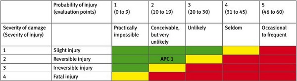
Fig. A 5-12
Application of the Risk matrix for Example 5.5
A Risk assessment yielding a Severity of injury Warc / Warc, prot = 1.3 "Reversible injury" and the Probability of occurrence at 16 points "Conceivable, but very unlikely" places the results in the green section of the Risk matrix (Fig. A 5-12). It is therefore permissible to perform the work tasks with PPEaA in the Arc protection class APC 1 on the basis of the evaluation approaches adopted.
A 5.6
Example 5.6: Industrial distributor
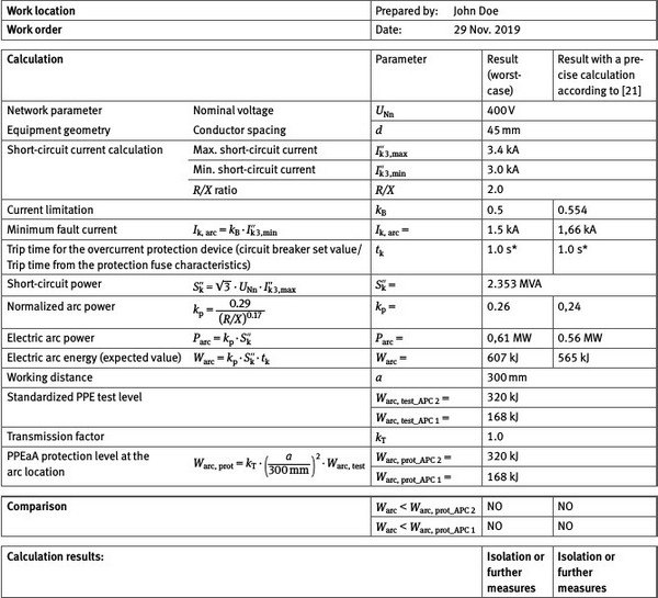
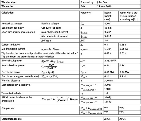
The following example depicts the calculation for a typical configuration behind an NH 315 A gG fuse. Various tasks are carried out behind the NH fuse on the installation in this example (refer to Fig. A 5-13). This ranges from simple adjustments on protection devices and equipment to replacement of the equipment itself. The work location is on the electrotechnical equipment for a cooling unit that lies behind an 86 m long cable.
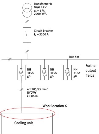
Fig. A 5-13
Industrial installation system overview
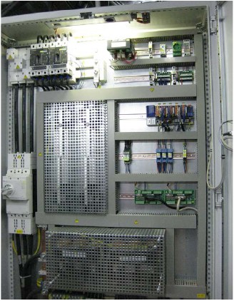
Fig. A 5-14
Industrial low voltage system (cooling unit control cabinet)
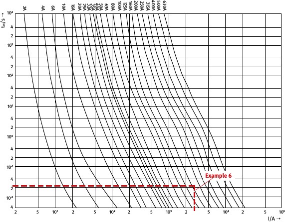
Fig. A 5-15
Mean time/current characteristic curves for the NH gL/gG AC 400V line protection fuse
being considered
Risk assessment of the planned activities
Phase 1: Is there a principle danger of exposure to persons due to electric arcing?
Yes
Work is carried out requiring physical contact with open live installation or in the vicinity of live equipment components, on which electric arcing can occur.
Phase 2: Initial evaluation of electric arc energy associated with the scope of activity or workplace. Is a calculation required?
Yes
None of the requirements listed in Section 1, in which the use of PPEaA can been dispensed with, have been fulfilled.
Phase 3: Apply the calculation methodology: Determine Warc, Warc, prot!
Execution of the required work steps will yield the results below (refer to Table A 5-8).
Table A 5-8 Results of the calculations for Warc and Warc, prot for Example 5.6 (low voltage industrial equipment)
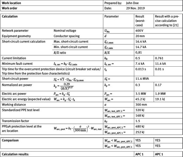
Note:
With a precise calculation, the characteristic curve for the protection fuse yields a time < 10 ms; the short-circuit duration is therefore established at 10 ms.
The calculation reveals that the expected arc energy is less than Warc, min = 50 kJ. Therefore, specific PPEaA is not required for the work task under consideration. An outfit of customary work clothing comprised of long-sleeved outer clothing and long pants is sufficient. However, it is recommended that protective clothing in the Arc protection class APC 1 be worn.
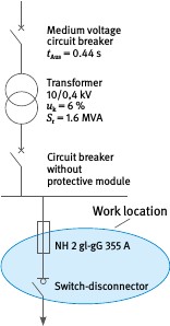
Fig. A 5-16
Equivalent circuit switchgear
A 5.7
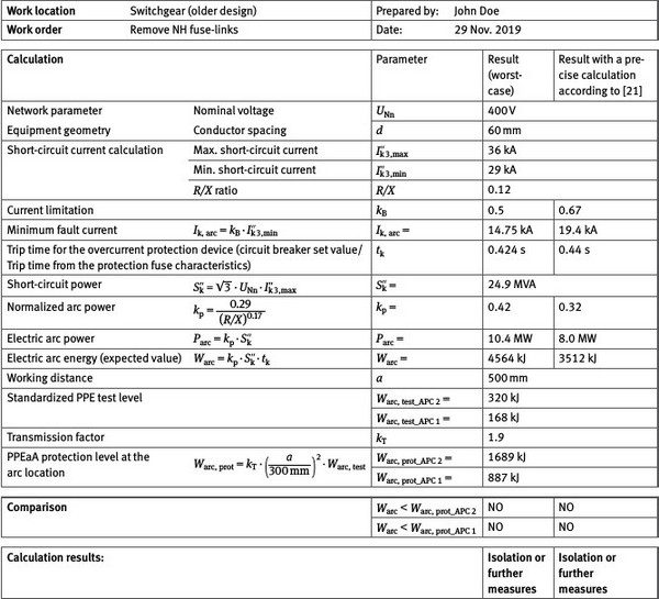
Example 5.7: Switching on systems of older design, not tested for electric fault arcing
Due to the high power demands in the industrial sector, equipment with high levels of short-circuit power are frequently deployed. Common transformer sizes for the transformation of medium to low voltage are 1.0 MVA, 1.6 MVA, 2.0 MVA and 2.5 MVA, and sometimes even as high as 4 MVA. As a consequence, these systems are capable of producing very high short-circuit currents. Relatively long trip times also exist to some extent.
The discussion below considers an exemplary case, in which a control panel (radial network) is isolated so that work can be performed on an underlying distribution system.
At first, the switch-disconnector assigned to the output circuit is actuated from outside by means of a lever (View a). Subsequently, the NH fuse-link is removed (View b) and the voltage-free state is determined (View c).
Risk assessment of the planned activities
Phase 1: Is there a principle danger of exposure to persons due to electric arcing?
Yes.
Resulting from a failure of the switching element and subsequent removal of the NH fuse-link from live installation, the potential for electric arcing cannot be ruled out.
Phase 2: Initial evaluation of electric arc energy associated with the scope of activity or workplace. Is a calculation required?
Yes.
None of the requirements listed in Section 1, in which the use of PPEaA can been dispensed with, have been fulfilled.

Fig. A 5-17
High-performance switchgear of older design; intended for industrial use
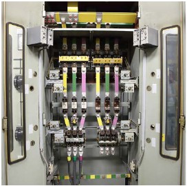
Fig. A 5-18
Opened panel
A 5.7.1 View a - Opening the load break switch
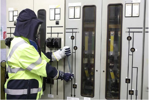
Fig. A 5-19
Opening the load break switch with a closed door by means of an operating lever
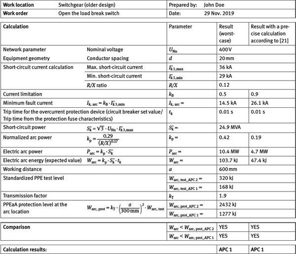
Phase 3: Apply the calculation methodology: Determine Warc, Warc, prot!
The calculation in Table A 5-9 reveals that APC 1 classified protective clothing is sufficient for opening the switch-disconnector. The protective properties of the door are not considered in this calculation because they are not quantifiable.
Note:
Arc flash testing on actual switchgear has revealed that doors have significant protective properties. In the event of strong electric arcing, the doors will presumably open and the arc energy will dissipate through the opening that emerges (directivity). For this reason, it makes sense to position one’s self in front of the installation so not to occupy the area where the doors will potentially open (stand off to the side). This will contribute to increasing the level of protection afforded the worker. Testing also revealed that the door hinges usually hold, while the opening emerges in the area of the locking mechanism.
Table A 5-9 Results of the calculations for Warc and Warc, prot for Example 5.7.1 (opening the load break switch)
A 5.7.2 View b - Removal of NH fuse-links
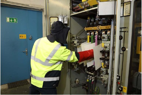
Fig. A 5-20
Removal of NH fuse-links, additional portable separators to isolate different potentials
Phase 3 (View b): Apply the calculation methodology: Determine Warc, Warc, prot!
Refer to Table A 5-10 for the results of the calculation.
Phase 4: Implement further measures towards reducing electric arc energy and the probability of injury due to electric fault arcing.
Suitable measures for reducing arc energy and the probability of injury due to electric fault arcing are not possible for the installation and the work situation in question. Therefore, proceed with Phase 5.
Phase 5: Estimate the probability of occurrence and the severity of injury due to electric fault arcing after the adopted measures have been implemented. Evaluate the residual risk and make a decision (Risk matrix).
Estimation of the severity of injury
It is assumed in this example that the calculation (according to Section 4) for the working conditions being considered will yield the following results:
| Protection level for PPEaA APC 2: | Warc, prot_APC 2 | = 1689 kJ (kT = 1.9; a = 500 mm) |
|---|---|---|
| Arc energy: | Warc | = 3512 kJ |
The relationship Warc / Warc, prot = 2.1 results in an anticipated severity of injury designated as "Reversible injury" according to Table A 5-11.
Table A 5-10 Results of the calculations for Warc and Warc, prot for Example 5.7.2 (removal of NH fuse-links)
Estimation of the probability of injury
Table A 5-11 Estimation of the probability of injury for 5.7
| Designation | Evaluation points | Explanation | |
|---|---|---|---|
| a) | Type/condition of equipment | 4 ... Unlikely | Equipment slightly dusty (no conductive deposits); condition assessment by visual inspection |
| b) | Technical measures | 2 ... Conceivable, but very unlikely | The use of bypass-resistant equipment (NH fuse handle with sleeve, mobile separators between the fuse-bases CAT IV voltage tester) |
| c) | Organizational measures | 2 ... Conceivable, but very unlikely | Implementation of company rules: Work and operating instructions are available Qualification of personnel: The deployment of qualified personnel for these tasks - specially trained switching personnel (qualified electricians) Overview circuit diagrams are available and up-to-date |
| d) | Personal measures | 2 ... Conceivable, but very unlikely | The use of PPEaA in the Arc protection class APC 2 |
| e) | Statistical influencing factors | 4 ... Unlikely | Limited space in critical areas: well-arranged structural design; critical areas are clearly identifiable Frequency and duration of work activities in areas where PPEaA protection in the Arc protection class APC 2 is not available: Limited to the removal of NH fuse-links - short work duration Findings from statistically sound and comparable electric arc incidents in the past: have not occurred to date while performing the activity in the organizational unit |
| f) | Ergonomic influencing factors | 2 ... Conceivable, but very unlikely | Experiences gained within the company through the use of different PPEaA or tools: PPEaA and the tools for working on live components were selected together with the participation of affected personnel |
| Summation: | 16 falls in the range (10 to 19) | Result: The anticipated probability of injury due to electric arcing can be termed "conceivable, but very unlikely" |

Fig. A 5-21
Application of the Risk matrix for Example 5.7
A Risk assessment yielding a Severity of injury Warc / Warc, prot = 2.1 "Reversible injury" and the Probability of occurrence at 16 points "Conceivable, but very unlikely" places the results in the green section of the Risk matrix (Fig. A 5-21). It is therefore permissible to perform the work tasks with PPEaA in the Arc protection class APC 2 on the basis of the evaluation approaches adopted.
A 5.7.3 View c - Determine the voltage-free state
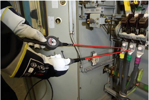
Fig. A 5-22
Determining a voltage-free state
The voltage-free state must be determined at the conclusion of the isolation process. In the context of Phase 1 of the Risk assessment, it must be assessed as to whether a hazard due to exposure to electric fault arcing exists. For the case at hand, this test is performed using a CAT IV voltage tester with extended tips. These are not necessarily required here, but it is considered standard for companies employing switching personnel because they afford a greater working distance. They are configured with very short metallic tips, whereby a bridging of the potentials between live parts in the case at hand cannot take place. The potential for electric arcing can be thus ruled out, so that determination of the voltage-free state can be done without PPEaA. Yet, because PPEaA was required anyway for the previous work step (Removal of NH fuse-links), it should also be used when carrying out this short process of determining the voltage-free state.
Because APC 2 PPEaA is required for work step b - "Removal of NH fuse-links" it follows that PPEaA will be used for all three work steps. The wearing of PPEaA is ergonomically unproblematic because the duration of the overall work being performed is only 5 to 10 minutes.
A 5.8
Example 5.8: Working on DC installations (UPS)
Working on UPS systems
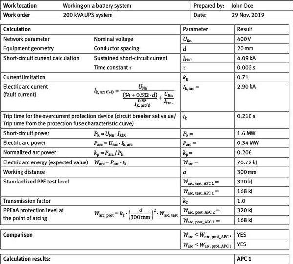
This example deals with work performed on a UPS system (uninterruptible power supply) of 200 kVA (displacement factor cos φ = 0.9, efficiency factor DC/AC = 0.9) with a high-performance battery in the intermediate circuit of the inverter. The intermediate circuit voltage equals 400 V (refer to Fig. A 5-23).
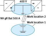
Fig. A 5-23
Principle circuit diagram for the UPS system for Work locations (fault locations)
1 and 2
Based on the output power from the inverter, an end-point voltage of 350 V and a prescribed discharge time (bridging time) of 15 min yields a battery discharge current (maximum battery current) of 571 A. Protection of the battery is provided for through the use of a fuse switch disconnector with a DC battery fuse NH gR Bat 500 A (500 V, frame size NH3).
The battery is comprised of 100 series connected 4 V battery cells. In the data sheet, the manufacturer specifies an internal resistance of 97.9 mΩ (0.98 mΩ/cell), which yields a prospective short-circuit current of IkDC = 4.086 kA.
Risk assessment of the planned activities
Phase 1: Is there a principle danger of exposure to persons due to electric arcing?
Yes.
When working on an inverter or in the vicinity of the battery, the potential for electric arcing cannot be ruled out.
Phase 2: Initial evaluation of electric arc energy associated with the scope of activity or workplace. Is a calculation required?
Yes.
None of the requirements listed in Section 1, in which the use of PPEaA can been dispensed with, have been fulfilled.
A 5.8.1
Working in the vicinity of a battery or directly on the battery cells (Work location
1)
Phase 3: Apply the calculation methodology: Determine Warc, Warc, prot!
When working in the vicinity of a battery or directly on the battery cells, a conductor spacing of d = 30 mm is assumed when introducing an electric arc short-circuit, which yields a current limiting factor of kB = 0.677 and an actual fault current (electric arc short-circuit current) of Ik, arc = 2.76 kA. Because the work location is not within the protection zone of the NH gR Bat fuse, the most unfavourable case for an exposure time tk = 1 s must be assumed (maximum exposure time or duration of time, in which a person is able to withdraw from the immediate danger area).
For electric arc power, the iteration calculation yields Parc = 358 kW, which corresponds to a normalized arc power of kP = 0.219. With a short-circuit duration of tk = 1000 ms, the resulting expected value for converted electric arc energy at the work location (fault location) is Warc = 358 kJ.
If electric arc power is calculated with a worst-case estimation (without considering the electrode gap) for the relationship of Parc = 0.25 PK with the network parameters for network voltage level, prospective short-circuit current and the short-circuit power at PK = UN・IkDC , then it follows that Parc, max = 0.25・1.634 MVA = 0.408 MW. The resulting expected value for arc energy is then Warc, max = 408.5 kJ.
The PPEaA protection level is determined from the arc energy test level with consideration given to the transmission relationships and the working distance a. If one assumes conditions related to the system volume where a rear panel effect primarily exists, which correspond to a transmission factor of kT = 1.5 and a distance of a = 300 mm, then an PPEaA protection level Warc, prot will result from the test levels Warc, test conforming to Warc, prot = kT・(a / 300 mm)2・Warc, test . For Arc protection class APC 1, Warc, prot_APC 1 = 252 kJ applies, and for Arc protection class APC 2, Warc, prot_APC 2 = 480 kJ applies. It follows then that PPEaA in the Arc protection class APC 2 is necessary for the work in question.
The calculations are depicted in the form of work steps in the overview Table A 5-12.
Table A 5-12 Summary of the example for work on UPS systems at Work location 1
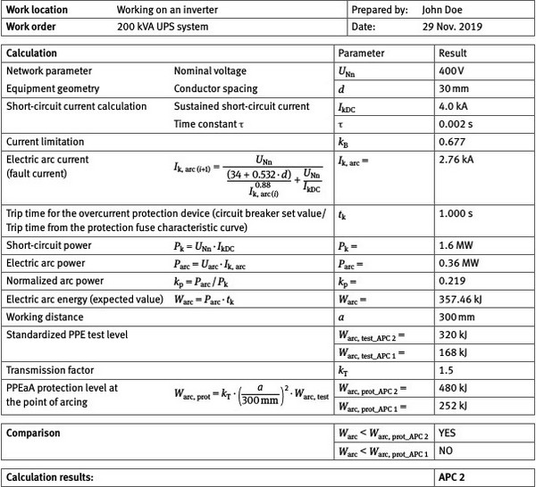
A 5.8.2
Working in the vicinity of the inverter (DC intermediate circuit, Work location 2)
Phase 3: Apply the calculation methodology: Determine Warc, Warc, prot!
At the fault location, a conductor spacing of d = 20 mm is assumed, which yields a current limiting factor of kB = 0.710 and an actual fault current (electric arc short-circuit current) of Ik, arc = 2.9 kA. The system is shut down by the fuse because the fault occurred within its protection zone. Using the manufacturer's data sheet results in an NH gR Bat 500 A fuse for the fault current of 2.9 kA with a trip time of tk = 210 ms (refer to Fig. A 5-24).
For electric arc power, the iteration calculation yields Parc = 337 kW, which corresponds to a normalized arc power of kP = 0.206. With a short-circuit duration of tk = 210 ms, the resulting expected value for converted electric arc energy at the work location (fault location) is Warc = 70.7 kJ.
If electric arc power is calculated with a worst-case estimation (without considering the electrode gap) for the relationship of Parc = 0.25 Pk with the network parameters for network voltage level, prospective short-circuit current and the short-circuit power at PK = UN・IkDC , then it follows that Parc, max = 0.25・1.634 MVA = 408,5 kW. The resulting expected value for arc energy is then Warc, max = 85.8 kJ.
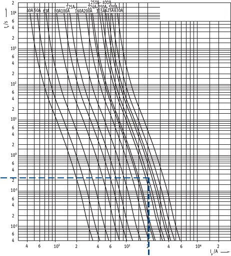
Fig. A 5-24
Mean time/current characteristic curves for the NH gR Bat line protection fuse being
considered
The PPEaA protection level is determined from the arc energy test level with consideration given to the transmission relationships and working distance a. If one assumes standard conditions related to a small-scale system volume (with side and rear panels), which correspond to a transmission factor of kT = 1.0 and a distance of a = 300 mm, then the PPEaA protection level Warc, prot will be identical with the test level Warc, test. The protection level under these conditions for PPEaA in the Arc protection class APC 1 are Warc, test = 168 kJ, so that work can be carried out at the Work location in question with PPEaA in the Arc protection class APC 1.
In the event of divergent system conditions, greater values for the transmission factor and the working distance will result, so that the protection level according to Warc, prot = kT・(a / 300 mm)2・Warc, test will also assume a higher level. It follows than that work under these circumstances with PPEaA in the Arc protection class APC 1 is possible.
The calculations are depicted in the form of work steps in the overview Table A 5-13.
Table A 5-13 Summary of the example for work on UPS systems at Work location 2
A 5.9
Example 5.9: Working on DC installations (traction network))
Working on a rectifier substation in the output circuitry downstream from the supply circuit breaker
In the DC supply system, each section of tracking line is supplied by a parallel connection (refer to Fig. A 5-25). Work is foreseen on substation A in the output circuitry. The substation is accordingly supplied from two sides: via supply line SL A as well as with supply line SL B via substation B and the tracking line FL.
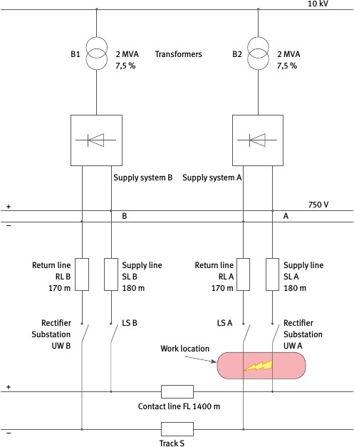
Fig. A 5-25
Equivalent circuit diagram for the DC traction power supply work location
Risk assessment of the planned activities
Phase 1: Is there a principle danger of exposure to persons due to electric arcing?
Yes.
For the work areas associated with substations A or B, the potential for electric arcing cannot be ruled out.
Phase 2: Initial evaluation of electric arc energy associated with the scope of activity or workplace. Is a calculation required?
Yes.
None of the requirements listed in Section 1, in which the use of PPEaA can been dispensed with, have been fulfilled.
Phase 3: Apply the calculation methodology: Determine Warc, Warc, prot!
Under consideration is the work-related introduction of a short-circuit in the output section of inverter UW A, downstream from feed circuit breaker LS A. With a two-sided supply, a fault circuit develops that leads via the parallel connection of the branch with feeding line SL A and circuit breaker LS A and of the branch with feeding line SL B, the substation B with circuit breaker LS B, the traction line FL, the fault location in substation UW A and the branch with return line RL B to substation UW B and the track rail S.
A suitable switching state is initially established for work in the substation, in which a one-sided supply is selected. In the parallel circuits, the branches with inverter UW A's supply line SL A and return line RL A each possess low resistance. For this reason, the feed circuit breaker for inverter UW A is switched off prior to beginning work. The level of short-circuit current is reduced accordingly so that, in the event of a fault, low power and energy levels will be converted into an arc flash.
When a short-circuit occurs, the location of the fault at the work location will be supplied only via inverter UW B (short-circuit electrical circuit via supply line SL B, closed circuit breaker LS B and contact line FL, fault location, track S and return line RL B. Shutdown of the fault takes place via circuit breaker LS B in the subsection of inverter UW B.
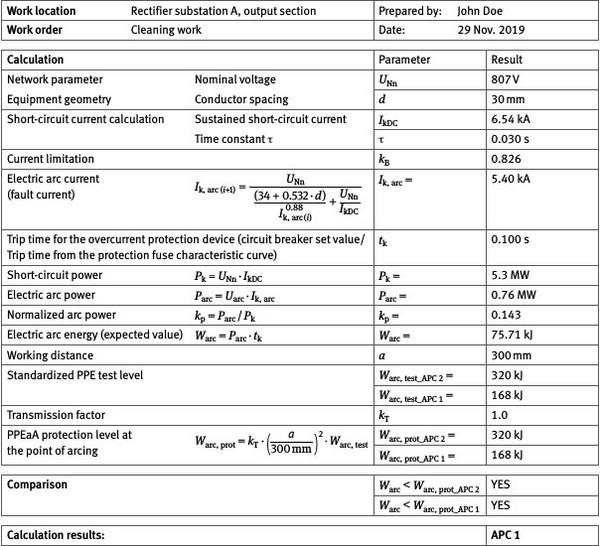
At the work location or fault location in question, a prospective short-circuit current of IkDC = 6.54 kA with a network voltage of 807 V has been determined and has also been verified by measurements taken during short-circuit testing. At the fault location, a conductor spacing of d = 30 mm is assumed, which yields a current limiting factor of kB = 0.826 and an actual fault current (electric arc short-circuit current) of Ik, arc = 5.4 kA. The circuit breaker LS B in inverter UW B (static trigger set at 5 kA) shuts down the fault circuit at a short-circuit duration tk = 100 ms (with di/dt protection, the circuit breaker switch-off time is generally even faster).
For electric arc power, the iteration calculation yields Parc = 760 kW, which corresponds to a normalized arc power of kP = 0.143. With a short-circuit duration of tk = 100 ms, the resulting expected value for converted electric arc power at the work location (fault location) is Warc = 75.7 kJ.
If electric arc power is calculated with a worst-case estimation (without considering the electrode gap) for the relationship of Parc = 0.25 PK with the network parameters for network voltage level, prospective short-circuit current and the short-circuit power at PK = UN・IkDC, it follows that Parc, max = 0.25・5,3 MVA = 1.325 MW. The resulting expected value for arc energy is then Warc, max = 133 kJ.
The PPEaA protection level is determined from the arc energy test level with consideration given to the transmission relationships and the working distance a. If one assumes standard conditions related to a small-scale system volume (with side and rear panels), which correspond to a transmission factor of kT = 1.0 and a distance of a = 300 mm, then the PPEaA protection level Warc, prot will be identical with the test level Warc, test. The protection level under these conditions for PPEaA in the Arc protection class APC 1 is Warc, test = 168 kJ, so that work can be carried out at the work location in question with PPEaA in the Arc protection class APC 1.
In the event of divergent system conditions, greater values for the transmission factor and the working distance will result, so that the protection level according to Warc, prot = kT・(a / 300 mm)2・Warc, test will also assume a higher level. It follows than that work under these circumstances with PPEaA in the Arc protection class APC 1 is possible.
The calculations are depicted in the form of work steps in the overview Table A 5-14.
Table A 5-14 Summary for the example of work in the outgoing branch of the rectifier substation
Referencing the current-time curve (Fig. A 5-10) results in a trip time t > 1 s, so it can be assumed that the maximum time relevant to the exposure equates to tk = 1 s (also refer to the remarks at the end of Sec. 4.2.2).