
Abschnitt 4.3 - 4.3 Requirements for Load Lifting Devices (LLD)
4.3.1 General information
The regulation area "Construction and Equipment" under the helicopter's primary cargo hook or, for example, from the cargo hook of the hoist fastened to the helicopter, certified for aviation purposes, is allocated to machinery and occupational safety and health law. This field also includes the Load Lifting Devices (LLD include slinging equipments and their components).
| Complex Load Lifting Device |
|---|
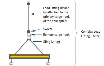 |
Load Lifting Devices that were placed on the market and put into service for the first time after 1st January 1997 are under the scope of the 9th Ordinance on the Product Safety Act (9th ProdSV). In this ordinance, the machinery ordinance, it is stipulated that machines and safety components must comply with the fundamental safety and health protection requirements of Annex I of the EC Machinery Directive (2006/42/EC), if they are to be placed on the market within the European Union. Slinging equipments and their components also count as Load Lifting Devices. In this way, the requirements of Annex I of the EC Machinery Directive are also binding for the manufacturer or his authorised representatives of Load Lifting Devices.
A manufacturer's declaration of conformity and an operating manual (instructions) for the use and for the maintenance must be present for Load Lifting Devices (LLD).
The dimensioning of the LLD must be fundamentally selected so that loads can be lifted, transported and deposited safely and failure due to fatigue and wear is excluded.
The LLD must be able to lift the load safely by positive fit and positive connection and equipped with aerodynamic stabilisers, if the rotation of the external load is not prevented in any other way.
The calculation factors for the dimensioning of LLD are to be identified taking the assignment-specific use factors into consideration. Load Lifting Devices for the operation with helicopters must absorb higher levels of force and stress compared to LLD for general hoisting operations due to dynamics, aerodynamics, number of cycles etc. Load Lifting Devices for hoisting operations can be used for the transport of loads with a helicopter, if the specific requirements with regard to dimensioning (e.g. maximum Working Load Limit) are taken into account.
LLD may only be used if the following markings are present:
information on the manufacturer
construction and material (if this is necessary for safe use)
CE marking
maximum Working Load Limit (WLL)
Each part that is not part of an assembly must be marked separately.
Furthermore, an operating manual must be present, which contains, for example, the following information:
intended use
reasonably foreseeable misuse
instructions for use, installation and maintenance
possible limits of use
load capacity, e.g. in case of containers for bulk goods
Insured individuals must observe the load handling equipment during the usage phase for visible defects (deformations, cracks or wear). The employer has to ensure that load handling equipment with defects that has an impact on safety is removed from further use.
4.3.2 Cargo hooks
Mechanical cargo hooks should be designed as positive-locking, self-closing and self-locking safety hooks when force is applied. They must be dimensioned and designed in such a way that:
safe lifting of the slinging equipments to be attached or the load is possible taking into account all expected load forces (load collectives),
the cargo hook is only directly loaded at the bottom of the hook,
an overlapping of, for example, lifting belts due to the hook size is avoided,
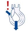
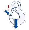
a spring-loaded safety catch using a protruding beak form fitted at the tip of the hook prevents unintentional unhooking,
a cargo hook beak should not or only slightly protrude from the hook's geometry.
In the case of cargo hooks with spring-loaded safety catches (safety traps) the possibility of the sling overturning exists in the event of unfavourable load situations. Self-locking hooks cannot be opened under load.
Basically, no cargo hooks should be used that are only locked by gravity.
Three types of cargo hooks can be differentiated:
Cargo hooks for attenuators, for load ropes and multiple leg suspension gear:
These cargo hooks are generally used for several rotations after each other (e.g. attenuators with load rope). They should be designed as self-closing and self-locking safety hooks. The force transmission of the rope line to the hook is carried out with a connection link.
Secondary cargo hooks with swivel at the load cable:
Secondary cargo hooks can have a cargo hook beak with spring-loaded safety catch. Unlike the safety hook, the secondary cargo hook is used during each rotation. In order to enable the lifting of several round slinging equipments and to be sufficient as ballast at the lower end of the load rope, it should be in an oversized design.
Electrical secondary cargo hooks with swivel:
Secondary cargo hooks with swivel and electric activation fulfil the same function as secondary cargo hooks with swivel. Electric secondary cargo hooks that comply with the state of the art lock the safety trap and can release the load (up to max. permitted WLL) electrically, if necessary.
4.3.3 Load ropes and ropes of slinging equipments
| Rule of technology by helicopter transport | ||
|---|---|---|
 |  |  |
| Protruding beak only for suspension gear (e.g. concrete buckets) | No beak: better | safety hook: more safe |
|---|
Ropes to manufacture Load Lifting Devices should be produced by manufacturers, who work according to a certified quality management system.
Load Lifting Devices and slings must be calculated and dimensioned so that they safely carry the load at maximum stress (maximum possible Working Load Limit), taking into account all expected load forces (load collectives), advancing age, mechanical wear and sling technology.
Ropes made of textiles
| Material | High modulus polyethylene | Polyester | Polyamide |
|---|---|---|---|
| Abbreviation | HMPE | PES | PA |
| Strength in N/mm2 | 360 | 110 | 90-95 |
| Ageing pa in % | 3% | >3% | 8-10% |
| Examples of use | |||
| Sling | X | ||
| Connecting element | X | X | |
| Load Lifting Device | X | X | |
| Damping element | X | ||
Possible applications for textile ropes/materials (selection)
Fibre ropes (plastic ropes) must consist of synthetic fibres.
Cables/chains made of steel
| Material | Chain grade 8 | Chain grade 10 | Steel wire rope |
|---|---|---|---|
| Abbreviation | G8 | G10 | rope galvanised |
| Strength in N/mm2 | 1100-1200 | 1200-1350 | 1770 |
| Ageing pa in % | no information | no information | no information |
| Examples of use | |||
| Sling | X | X | X |
| Connecting element | X | X | X |
| Load Lifting Device | X | X | X |
| Damping element | |||
Possible applications for cables/chains made of steel (selection)
Only low-torque rope constructions made of steel or textile materials may be used to manufacture Load Lifting Devices. Low-torque construction prevents a rope from being able to rotate on its own due to the load on the secondary cargo hook.
If no low-torque constructions are used as slings, these may only be very short slings.
The reaction (flight behaviour) of a lifting or slinging device to a helicopter's forward movement is essentially determined by the material of the rope, the rope's cross section and the distribution of mass between rope and secondary cargo hook.
| Flying up (synthetic and steel rope) |
|---|
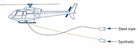 |
Load ropes made of textile materials (synthetic fibres) with a circular cross section offer much better controlled and less aggressive flight behaviour due to the material characteristics compared with steel ropes. They are characterised by slower movements and an extremely low oscillation behaviour (upward swinging of narrow objects in the air stream). Cross sections that are not circular, e.g. rectangular cross section (lifting belts) are not to be recommended, as they swing up or fly up aggressively, especially in the case of descent flight.
| Description | Principle |
|---|---|
| Circular cross section Best aerodynamic behaviour.  |  |
| Oval cross section Problematic. "Wobbles" during flight and produces relatively strong lift.  |  |
| Rectangular cross section Extremely problematic during use as load rope. Strong vacillations (vibrations perceivable on pitch or stick), accessories and nooses can be damaged. Strong lift and strong whipping.  | 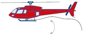 |
| Cross sections of multiple legs (round, oval or rectangular) Multiple leg load rope, extensions or long-legged slinging equipments vibrate strongly and produce very high resistance = lift. | |
In order to minimise the uncontrolled upsurge of load ropes in case of sudden relief (e.g. loss of load) and risk of damage to the helicopter or load rope associated with this, the following possibilities exist:
use of low-torque load ropes or rope constructions with low elongation (< 2 %) (use of e.g. polyamide lifting belts or polypropylene braided sheathing as Load Lifting Devices or slinging equipments is questionable and not to be recommended)
use of long load ropes (Long Line load ropes)
positioning of damping elements between helicopter and Load Lifting Devices
in case of rope combinations the load rope with the lowest mass on top and the greater mass fly at the bottom
positively influence upsurge behaviour by attaching a specific mass (additional mass) to the secondary cargo hook
selection of load ropes with increased carrying capacity (WLL)
stiffening of the rope
Electric cables should be placed within the rope geometry for electromechanical functions.
To minimise the impact of hard blows to the load rope, attenuators (shock absorbers) are used. This can however favour the effect of sudden upward movement, which is especially undesirable in the case of short ropes.
4.3.4 Rope end connections
Rope end connections should be produced by manufacturers, who work in accordance with a certified quality management system.
Rope end connections must be suitable for the respective intended purpose and comply with the rules of technology.
The following items are used:
The spliced end rope - it is a break-proof, permanent, non-detachable connection of the rope end with the rope by braiding the individual strands (rope parts). It transfers 85 % of the minimum breaking force of the rope in the case of standard-compliant versions. Splicing work may only be carried out by trained personnel.
The aluminium ferrule - it is one of the most common rope end connections and transfers 90 % of the minimum breaking force of the rope in the case of standard-compliant versions. The pressed sleeve should end cylindrically tapered on the open rope.
Aluminium ferrule 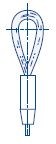
The spliced core-cover in textile bound ropes - it is a break-proof, permanent, non-detachable connection of the rope end with the rope by introducing the tapered rope end into the core of the same rope. It transfers 85 % of the minimum breaking force of the rope in the case of standard-compliant versions. Splicing work may only be carried out by trained personnel.
The flemish eye (in German "Flämisches Auge") - it is a special form of rope end connection. Strands are placed here in the opposite direction to a rope eye and fixed with a pressed sleeve made of steel. The advantage of the flemish eye is the considerably higher carrying capacity due to the symmetrical force distribution. In the case of standard-compliant manufacture, up to 100 % of the minimum breaking force of the rope can be transferred.
Rope loops are fundamentally to be executed with a suitable thimble. This must have an adequate width and match the respective fitting. As textile ropes in particular do not have any dimensional stability, thimbles must be executed here in a very dimensionally stable manner or with a welded-in wedge.
| Pointed thimble of form A with rounded tip for steel ropes |
|---|
 |
4.3.5 Lifting belts and round slinging equipments
Strap fabric for lifting belts and round slings must be manufactured from synthetic fibres only. They are mainly made of polyester (PES) for use with helicopters. Materials such as polyamide (PA) or polypropylene (PP) are not suitable because of too much stretch and too high moisture absorption.
Lifting belts tend to oscillate during inflow due to their rectangular cross section and are sensitive to flattened or twisted fastening.
Round slings are applicable in a versatile way and can therefore be attached even if somewhat twisted, stacked or bundled.
The carrying capacity of a lifting belt or a round sling in the type of slinging "Direct" is indicated by the colour of the round sling's cover or an individual part of the sewn strap.
The maximum Working Load Limit (WLL) of a flat woven lifting belt, a lifting belt unit or a round sling for assignments with helicopters must be determined by the user from the WLL of the lifting belt or the round sling by multiplication with the assignment-specific use and sling factors before the respective assignment.
Loops on the ends of the lifting belts can be reinforced in order to protect the loop's inner surface against damage during lifting and the tying point in the noose.
Suitable reinforcing materials are, for example, loop or strap fabric, leather or other resistant material.
The synthetic fibres the lifting belt was manufactured from are prone to a deterioration of their properties, if they are exposed to radiation with ultra-violet light (e.g. sunlight). Flat woven lifting belts or round slings should not be exposed to direct sunlight or sources of ultra-violet radiation for longer than necessary or stored under their influence.
Storage should be on a shelf in clean, dry and well-ventilated surroundings, away from heat sources, without contact with chemicals, fumes or corroded surfaces (e.g. rust deposits).
The marking of a lifting belt or a round sling must be legible and indelible on a label that is fastened directly to the lifting belt or the round sling. For reference purposes, there is a further label underneath a seam.
The following minimum details are needed for the user:
carrying capacity of the lifting belt or the round sling in case of direct attachment
material (polyester, polyamide, polypropylene)
grade of fittings
nominal length in metres (m)
name of manufacturer, symbol, brand name or other unambiguous identification
traceability code (for the individual basic elements)
number of the European standard
maximum angle of inclination of a leg to vertical in the event of multiple leg round sling suspension gear
4.3.6 Round steel chains
Round steel chains should be produced according to the relevant standard, be made of high-strength steel and short-linked.
The maximum Working Load Limit (WLL) of a sling or Load Lifting Devices made of round steel chains for assignments with helicopters must be determined by the user from the WLL of the sling or Load Lifting Devices by multiplication with the assignment-specific use and sling factors before the respective assignment.
If used as a sling with cording, the maximum Working Load Limit (WLL) is limited to 80% of the marked Working Load Limit.
Round steel chains are particularly suitable for fastening loads with sharp edges or rough surfaces (e.g. iron bars). If necessary, they must be secured against slipping due to low friction between sling chain and e.g. a load of metal.
Multiple-leg sling chains must always be stably attached to the load with all individual legs.
Sling chains that are not in use should be stored hanging in a specific rack.
As well as the regular inspection of the round steel chains by an expert/an authorised inspector according to the Ordinance on industrial safety and health, round steel chains that are used as slinging equipments must undergo a special inspection (e.g. non-destructive testing procedure) for absence of cracks. This is to be carried out at intervals of max. three years, taking the manufacturer's instructions into account.
4.3.7 Personnel Carrying Device System
Personnel Carrying Device Systems (PCDS), which are used to transport persons as external load on the helicopter, are to be hooked into the cargo hook or the rope hoist.
Personnel Carrying Device Systems must have an airworthiness permit.
The airworthiness permit for PCDS of complex design - for example, cages for personnel transport, nets, Personnel Carrying Devices for double cargo hooks (quick release systems) or other mountain rope systems without a standard conformity (EN conformity) - has to be carried out in accordance with the criteria of a significant constructional modification and is to be certified according to CS 27/29.865 and the corresponding guidelines.
The airworthiness permit for PCDS of simple design - for example, Personal Protective Equipment against falling in the sense of the EC Directive 89/686/EEC, to be used for max. two persons and manufactured in compliance with a harmonised EN standard or means to secure a person operating the hoist or the cargo hook in the cabin, provided that the Personal Protective Equipment against falling used has an EN-compliant permit - can be carried out in accordance with a simplified permit procedure.
The unrestricted compatibility between the helicopter and the PCDS is to be determined by the employer. This includes, in particular:
the unimpeded mounting and demounting of the PCDS in the helicopter cabin,
the inclusion of the PCDS in the hoist hook,
the inclusion of the PCDS in the primary cargo hook,
so that an unscrewing or tilting in the cargo hook is excluded.
4.3.8 Other Load Lifting Devices
Adjustable traverses must be equipped with form-fit and force-fit safeguards of the moveable parts. Where necessary, they are to be fitted with aerodynamic stabilisers.
If reusable Big Bags (FIBC) are used, these must comply with DIN EN ISO 21898 (safety factor of at least 6). In addition, for the helicopter transport:
the lifting belts are to be adequately dimensioned (four-leg suspension gear)
the lifting belts are to be at least 1 m long and sufficiently sewn at the ends
the lifting belts are continuously sewn all round, crosswise on the bottom and up to the beginning of the loops
the lifting belts are to be sewn between a double bottom
the necessary manufacturer's details (e.g. maximum Working Load Limit, pictograms for lifting) are to be mounted or printed on a large scale and permanently on the sides
no openings are to be planned on the bottom
4.3.9 Individual parts for complex Load Lifting Devices (connectors)
The connection means (shackles, connex or connection links) must be suitable for the planned assignment and calculated and dimensioned in such a way that they safely carry the maximum load taking into account all expected load forces (load collectives), advancing ageing and mechanical wear.
Shackles have not proved their worth for the permanent connection of e.g. Long Lines. It is possible that they can be opened by blows or other external impacts.
Shackles must be secured with additional devices for force-fit security.
These can be, for example, cable ties, safety splints or safety wires.
Short-term connection with shackles must be checked for proper condition before each assignment.
Swivels or rotating swivel hooks can also be used as connecting links. These are to be checked for their ease of operation of the rotating insert before the assignment.
Rotating swivel hooks with ball bearing are designed exclusively for slinging equipments. They are only used to offset torsion in multiple-leg suspension gear.
Every connector must - without negatively influencing the properties of the individual part - be marked legibly and permanently at a place, which is not impeded by use.
This marking must contain at least the following information:
nominal size
the grade code number
name, sign or brand of the manufacturer
traceability code
CE marking