Abschnitt 4.1 - 4 Protective measures for industrial robots and robot systems
4.1 Hierarchy of protective measures
Similar to other systems, the totality of protective measures on a robot system is often a combination of measures being applied by the system designer in the design stage, e. g. protective devices, and measures which have to be taken by the user, e. g. behavioral requirements and personal protective equipment. But, as a matter of principle, measures which can be considered already during the design stage have priority over all measures which have to be taken by the user.
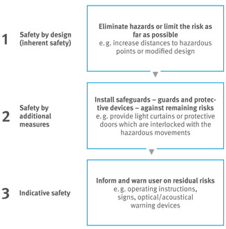
Explanations as to a systematic procedure for specifying protective measures by the designer are described in EN ISO 12100. One of the main contents is the hierarchy of the measures to be taken (Figure 25). The 3-step method describes that hazards are to be eliminated by design first (safety by design). If this is not entirely possible, safeguards have to be provided. Only if neither design measures nor safeguards can completely eliminate the hazards, indicative measures may be applied.
4.1.1 Modes of operation of robots (without periphery)
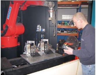
Generally, it is unavoidable that setting work with robots cannot be exclusively done from outside the safeguarded space but has to be carried out inside the safeguarded space as well. Therefore, operation modes for setting and programming have already been provided for each "bare" industrial robot which can then be installed by the system designer.
According to EN ISO 10218-1, industrial robots have to be equipped with the modes of operation shown in table 1. For the modes of operation T1 and T2 as well as for special operation modes, skilled personnel have to be deployed.
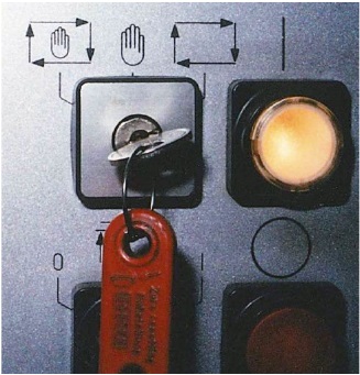
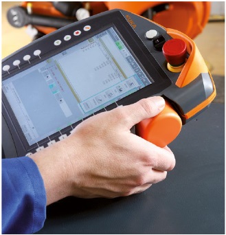
For selecting the modes of operation, a lockable mode selection switch has to be provided which can be removed in each position (Figure 26). Alternative selection devices such as e. g. access codes are also permissible, if they provide an equal level of safety. Attention should be paid to the control safety (category and PL) and the possibility of defeating protective measures (foreseeable misuse).
Selecting the high operating speed in operation mode T2 requires an additionl pressing of the button, e. g. on the teach pendant, and the measures mentioned in Table 1. The option to use the high operating speed expires as soon as the enabling switch remains non-activated over a period of more than 5 minutes. If a return to high operating speed is intended, it has to be preselected again by a rotary switch or by a push button. The demanded time monitoring of 5 min is no safety function.
Another feature of operation mode T2 is that with parallel use of this operation mode on several robots in one cell, the overlapping of ranges of motion represents a high risk. A safe stand has to be ensured for each operator.
The reduced speed of 250 mm/s during setting and programing which is indicated in Table 1 refers to the movement, measured at the robot’s tool holder. Generally, only a bumping hazard exists.
| Mode of operation | Protective measure | ||
|---|---|---|---|
| Manually reduced speed (T1) e. g. for setting and programming | Safeguards may be open or ineffective |  | |
| ⦁ | separate position of mode selection switch and | ||
| ⦁ | reduced speed *) (≤ 250 mm/s) in conjunction with enabling switch and hold-to-run control | ||
| Manual high speed (T2) e. g. for testing with operating speed | Safeguards may be open or ineffective |  | |
| ⦁ | separate position of mode selection switch or additional mode selection switch and | ||
| ⦁ | travel speed up to full operating speed and | ||
| ⦁ | hold-to-run control in conjunction with enabling device and | ||
| ⦁ | protected position for the machine setter, i. e. at least a distance of 0,5 m between fence and robot, e. g. by restricted range of motion (see also clause 4.2.1.3) | ||
| Automatic | Safeguards have to be closed or effective | 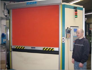 | |
| ⦁ | separate position of mode selection switch | ||
Reduced speed in operation mode T1 should be provided wherever possible according to the current state of the art (clause 4.1.3).
Tab. 1 Modes of operation [F]
In case of crushing or shearing hazards, e. g. when positioning a device, this speed should be further reduced according to the risk assessment.
The speed value of the reduced speed (250 mm/s) should be monitored by a safe control system (see clause 4.1.3). EN ISO 10218-1, however, also permits the possibility that the speed is not safely monitored and that the safety of persons is solely ensured by the safe enabling switch. Whether or not this option is applied results from the risk assessment, in particular with regard to the stopping distances.
In collaborative operation, the reduced speed shall always be safely monitored (clause 5).
4.1.2 Enabling device
An enabling device (enabling switch) is an additional manually operated control device which is used in conjunction with a start control and which, if being continuously actuated, permits a machine function. An actuation of the enabling device alone must not initiate a movement. The enabling device has to be designed in a way to allow machine movements only in a specific position. In older systems, two-position versions of enabling devices can still be found. (Table 2).
For industrial robots which have been produced after EN ISO 10218-1 came into effect (Feb. 2007), only three-position enabling switches may be applied. For old machine stocks and possible retrofitting, no European regulations are available. But there may be internal company provisions. Due to the accident history or the consistency of the equipment, they may stipulate a particular type of design. If nothing comparable exists, the decision should be taken by considering the existing risks. Three-position enabling devices switch off safely even in case of "seizing". Two-position enabling
| 2-position permitted for old stock only | 3-position for new and old systems | |
|---|---|---|
| Position 1 neutral position | Off-function (control element is not actuated) | Off-function (control element is not actuated) |
| Position 2 release position | Enabling function (control element is actuated) | Enabling function (control element is actuated in its center enabled position) |
| Position 3 panic position | - | Off-function (control element is actuated beyond its center enabled position) |
Tab. 2 Types of enabling devices
switches may offer ergonomic advantages when being continuously actuated for a longer time since no pressure point has to be kept. In case of very confined spaces, the selection of a three-postion design should be preferred (reaction time, seizing).
The functions indicated in Table 2 solely refer to the switching device. The further processing of the signals has to proceed in safe technology, e. g. not via standard bus systems. If switching back from the third into the second position on actuation of the three-position type, the enabling function must not generate an enabling signal. No movements must be initiated by the enabling device alone. An additional control device, e. g. hold-to run control, is required.
The signals of this additional hold-to-run control do not need to be processed in "failsafe technology". This also means that just pressing the enabling switch in the enabling position can enable a start of the robot movements even if the actual hold-to-run control key has not yet been actuated.
Although this must not be planned as intended purpose, it may result from the low safety requirements for the hold-to-run control, e. g. due to a control error that occurred over time. This fact should be mentioned in training courses for employees.
If not specified by the risk assessment, enabling devices and hold-to-run control keys for axis travel do not need to be designed as two-hand control devices.
It can be assumed that only the programmer is present in the hazard zone during setting/programming. Accordingly, the protective measures mentioned in Table 1 can be considered as protection for the programmer. If further persons have to stay in the hazard zone due to technological reasons, additional protective measures have to be provided, e. g. additional enabling switches.
An interface for the connection of further enabling switches should be provided by the machine manufacturer from the very start in order to allow subsequent expansions.
4.1.3 Functional safety of the control system
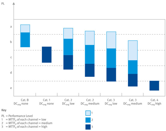
For safety-related parts of control systems, the product standards for industrial robots EN ISO 10218-1 and EN ISO 10218-2 require single-fault safety with partial fault identification. At the same time, information is given that these requirements are met by measures according to EN ISO 13849-1 or EN 62061. The following safety-related control system performance is indicated:
PLd (Performance Level d) associated with structure category 3 or
SIL 2 (Safety Integrity Level 2) associated with hardware fault tolerance 1.
In most cases, these requirements necessitate a dual-channel control structure according to Figure 29. Thus, the free selection of the category or PL or SIL by means of a risk graph (Figure 30) is limited.
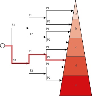
In a justified individual case, it is allowed to deviate from these provisions as a result of a comprehensive risk assessment for the robot system and its application. For selecting an alternative control category, /PL/SIL, the risk graphs according to EN ISO 13849-1 can be used as an aid (Figure 30).
The safety-related parts of control systems include e. g.:
electric interlockings of protective devices
enabling switches
limits or monitoring of the range of motion of robots
limit or monitoring of speed
limit or monitoring of force for collaborative robots
signals from light curtains
emergency-stop
safety stop
mode selection switch
Examples of determining the Performance Levels, see clause 4.3
4.1.4 Safely monitored robot control system
A safe electronic protection system on a microprocessor basis offers a number of advantages in comparison with contact-based electro-mechanical technology, e. g.:
no wear out of limit switches
enhanced diagnostic options
shorter reaction times possible
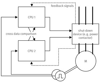
The electronic program control (task program) designed for production tasks does, however, normally not fulfill the safety requirements (see clause 4.1.3). This requires an independent superior dual channel protection system. The required technical effort has been considered to be unjustifiable for a long time. New powerful microprocessors, however, also enable the safe monitoring of industrial robots.
Key
| S | = | Severity of injury |
|---|---|---|
| S1 | = | Slight (normally reversible injury) |
| S2 | = | Serious (normally irreversible injury or death) |
| F | = | Frequency and/or exposure to hazard |
| F1 | = | Seldom-to-less often and/or exposure time is short |
| F2 | = | Frequent-to-continuous and/or exposure time is long |
| P | = | Possibility of avoiding hazard or limiting harm |
| P1 | = | Possible under specific conditions |
| P2 | = | Scarcely possible |
The following safety functions are provided by most robot manufacturers:
Safely reduced speed, e. g. monitoring of tool mounting flange when setting with 250 mm/s or in collaborative operation.
Safe cartesian restriction of range of motion, e. g. for safely limiting the range of motion or for determining a restricted space (see clause 4.2.1.3).
Safe axis-specific restriction of range of motion, e. g. for safely limiting the range of motion or for determining a restricted space (see clause 4.2.1.3).
Safely monitored stop, e. g. by actuating protective devices (see clause 4.1.5).
Safe deceleration ramps, e. g. for emergency stop, enabling devices
For collaborative robots in the function Power and Force Limiting, a safely monitored force limitation is additionally required.
4.1.5 Protective stop
Each industrial robot shall have an option for the connection of external protective devices, e. g. for the connection of light curtains and and protective door switches. This interface is called protective stop input. It has to be physically available in addition to the emergency stop input, e. g. by additional terminals.
The stop reaction of the robot in case of a protective stop has to take place according to EN 60204-1 in stop category 0 or 1 [9]. Stop category 2 may be applied in addition if the standstill is safely monitored.
4.1.6 Emergency-stop
Industrial robots have to be equipped with one or more emergency-stop devices. At the same time, an option for the connection of the external emergency-stop devices has to be provided, e. g. a terminal.
The term "Emergency-Off" as used e. g. in the former German DIN EN 775 must not be applied for new systems anymore. Emergency-Off is reserved for electric (galvanic) isolation from the energy supply.
The emergency-stop circuits have to be designed with failsafe technology according to EN 60204-1. The functional safety of the emergency-stop circuit has to be designed according to EN ISO 10218-1 in single-fault safety (see clause 4.1.3). Emergency-stop devices have to be clearly visible and easily accessible. They have to be provided at least at each place of operation.
After unlocking the emergency-stop control device, the system shall not immediately restart. Restart may only take place after actuation of an additional start device.
4.1.7 System-Emergency-Stop
Normally, the emergency-stop circuit has to be designed in such a way that on actuation of the emergency-stop, the hazardous movements and the hazardous process functions of the entire system are stopped. In case of very spacious robot systems, it is permissible to divide the emergency-stop devices into defined sections (see EN ISO 11161). The precondition is that they are identifiable as partial sections by the constructual layout of the system. In addition, signs have to be fixed at the emergency-stop devices. The personnel has to be familiarized with the effects of operation of these emergency-stop devices by appropriate training.
Particular attention has to be given to the interfaces of adjoining system parts. If necessary, emergency-stop circuits need to be effective at the interfaces on adjoining system parts, if their further operation represents a hazard (e. g. material handling). See clause 2.3.
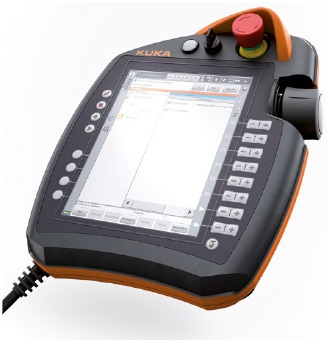
4.1.8 Teach pendant (TP)
Each teach pendant has to be provided with an emergency-stop device. The safety-related lines which are inside the flexible supply line of the teach pendant, e. g. emergency-stop and enabling device, have to be protected against short and cross circuit, e. g. by redundancy and monitoring.
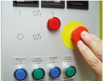
In practice, occasionally teach pendants with grey emergency-stop actuators can be encountered, which are not permitted according to EN ISO 10218-1. Emergency-stop devices shall be marked in red on a yellow background. Even wireless-operated teach pendants shall have a fully effective emergency-stop device which shall be marked in red/yellow as well.
Inactive plug-in teach pendants have to be stored in such a way that inadvertent actuation of the emergency-stop control device on the pendant which is inactive at that time is prevented. The system supplier has to provide relevant information in the operating instructions. The user of the system has to instruct the employees accordingly.
For linked systems comprising several robots, it may be necessary to disconnect the teach pendant during the running operation if it is needed at a different station or for a different robot.
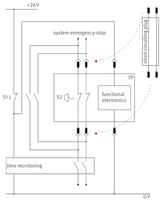
Without additional control measures, the removal of the plug would lead to an immediate standstill of the entire system. The reason is the emergency stop device on the teach pendant which is designed as closed circuit. In this case, a circuit for the temporary by-passing of the relevant emergency-stop circuit is required. The relevant standards do not include provisions on how such a circuit has to be designed. In the course of the risk assessment, however, the sticking of pushbuttons which are used for bypass should be taken into account as well as the deliberate locking for reasons of convenience.
A monitoring of time is thus reasonable in any case. Figure 34 shows an example circuit with a dummy plug (short-circuiting plug). Since the time monitoring has no direct influence on the safety function, an off-delay relay or an electronic component (e. g. PLC) can be applied. Isolation has to be considered. The time setting should provide additional time for replugging (e. g. several minutes), so that no unintended shutdowns occur.
4.1.9 Stop as quickly as possible
The Machinery Directive and EN 60204-1 unanimously require a stop as quickly as possible for applying the stop function for emergency-stop. The term "as quickly as possible", however, is extensible and requires additional consideration.
The interconnection of the emergency-stop signals or protective door signals with the immediate isolation of energy (stop category 0) and the simultaneously acting mechanical brakes may cause a fast braking process but leads to wear of the brakes. This impairs the safety of the system. A controlled stop on which the energy to the machine actuators is maintained in order to achieve a stop spares the machine. Energy is only interrupted when the standstill has been achieved (stop category 1). The electronic drive units required for braking are, however, normally not suited for safety functions. The case of failure, where the electronics fail at the moment of emergency-stop or on opening the protective door, is rather unlikely but cannot be excluded. As a consequence, this may lead to an uncontrolled running down or further acceleration of the drives.
| Stop function | Description | Suitability for safety functions |
|---|---|---|
| Stop category 0 | Stopping by immediate removal of power to the machine actuators | Yes |
| Stop category 1 | A controlled stop with power available to the machine actuators to achieve the stop and then removal of power when the stop is achieved. | Yes |
| Stop category 2 | A controlled stop with power left available to the machine actuators | Yes, but with additional measures |
Tab. 3 Stop functions according to EN 60204-1
Since the drive control electronics are also used during normal operation, it is assumed that such faults become already apparent during production by malfunctions. For the time being, safe time monitoring of the deceleration ramps is still sufficient. More recent control systems, however, already dispose of so-called deceleration ramp monitoring which can also monitor the course of the deceleration ramp.
Applicable standards do no specify, which time function is to be selected for the electronically controlled stop. A stop on a geometrical path is just as admissible as a stop at the current limit. The decision is left to the manufacturers risk assessment. Isolation of energy after the time scheduled has to be ensured. This necessitates safe time elements.
For enabling switches, stop category 0 or stop category 1 with monitored deceleration ramp should be selected.
4.1.10 Axes limiting
According to EN ISO 10218-1, at least the main axis, i. e. the axis with the largest extension, has to be provided with the option to mount mechanical fixed stops. For axes two and three (axes with second and third largest extension) there has to be the option to provide mechanical, electromechanical or electronic axes limiting.
Where and to which radius axis limiting for the safety of persons has to be provided, depends on the risk assessment of the system. This requires the specification of the so-called restricted space according to EN ISO 10218-1.
Maximum space: space which can be swept by the moving parts of the robot, as defined by the manufacturer plus the space which can be swept by the end-effector and the workpiece.
Restricted space: portion of the maximum space restricted by limiting devices that establish limits which will not be exceeded.
Limiting devices by means of the control system have to be designed in failsafe technology (see clause 4.1.3).
In new systems, axis limiting as shown in Figure 35 is rarely used today. Most of the time, safely monitored robot control systems are used (see clause 4.2.1.3).