
Abschnitt 4.3 - 4.3 Hose assemblies
4.3.1 General
Hose assemblies are only used on machines and vehicles, if hydraulic connections are required between moving parts of a hydraulic system or if an easier replacement of power units (e. g. auxiliary power units on earth-moving and farm machines) is wanted (see figure 12). Using hose assemblies can also reduce pressure peaks in the hydraulic system or compensate vibrations between individual parts.
In general, hoses consist of an elastomer compound of internal and external rubber layer and pressure carriers consisting of one or several layers.
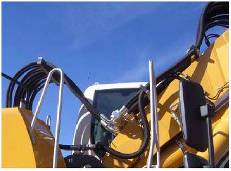
Fig. 12
Hydraulic hose assemblies on an excavator
Plastic hoses are used as well having technological advantages and disadvantages (see also section 4.3.9).
The term hose assembly describes the assembly and the unit of hose and fitting mounted afterwards.
Hose line = Hose + Fitting
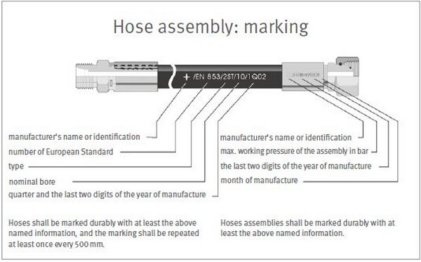
Fig. 13
Structure and labeling of a hose assembly
Faulty integration, ageing, and mechanical damage can result in the hose assemblies bursting. Thus, corresponding care should be exerted when selecting, assembling, mounting, and operating hose assemblies.
A hose has to be labeled consecutively and durably as follows, see DGUV Regel 113-020 "Hydraulik-Schlauchleitungen und Hydraulik-Flüssigkeiten - Regeln für den sicheren Einsatz" (Hydraulic hose assemblies and hydraulic liquids - Rules for safe use):
manufacturer sign,
hose type,
nominal width,
date of manufacture (quarter and year), as well as the
number of the relevant hose standard.
A hose assembly has to be labeled durably as follows:
manufacturer’s name or short sign,
maximum operating pressure with indication of the unit,
date of manufacture (year/month), see also DGUV Regel 113-020 or DIN 20066 "Fluidtechnik - Hydraulikschlauchleitungen" (Hydraulic fluid power - Hose assemblies - dimensions, requirements).
 | Note |
|---|---|
| Hoses and hose assemblies of unknown origin and/or with incomplete marking must not be used! | |
4.3.2 Selection of hose, fitting, and hose assembly for replacement
In principle, hoses have to be replaced in accordance with the manufacturer’s instructions. If no manufacturer details are available, the following procedure has to be followed:
Hose, fitting, and hose assembly have to be selected in such a way that
the admissible maximum operating pressure of the individual components is not exceeded for the operating conditions to be expected taking account of pressure peaks,
the operating pressures for which the control system has been designed are taken into account,
the thermal resistance is ensured,
changes in lengths and outside diameters of the hoses were taken into account,
the minimum bending radius is adhered to (depending on hose type and nominal width),
abrasion characteristics are considered,
the cross-sections are sufficiently dimensioned, so that no inadmissible dynamic pressures are generated that for example could impair the free return flow to the tank,
the compatibility of hose and sealing materials with the hydraulic fluid used is given,
only parts are used that comply with the requirements of European or international product standards, such as EN, ISO, SAE standards,
designs of hose assembly fittings consisting of a (drilled) pipe socket with olive are not used, as they do no longer correspond to the state-of-the-art and led to accidents due to slipping tools in the past.
| Note |
|---|---|
| It has to be checked, if the hose assembly is suitable for the intended use regarding pressure and flow. | |
4.3.3 Creating a hose assembly
It is recommended to purchase hose assembies as fully assembled parts.
If a hose assembly is self-made, it has to be observed that the selected parts (hose and fitting) are compatible regarding their dimensions, shape, and pressure stage. For this, it is imperative to observe the provisions of the manufacturers of hose and fitting. Proof of safe function must be furnished by an appropriate test procedure (see section 4.1.2 of DGUV Regel 113-020).
If the integration is self-conducted, only equipment and devices approved by the fittings manufacturer must be used for this purpose (see figure 14). A safe hose integration furthermore implies detailed knowledge of the integration procedure, the devices, and parts. Conducting the integration without this knowledge and without these devices is negligent and inadmissible from a safety point of view.
The so-called "improvised cobbling together" of hose assemblies on the bench vice is negligent!
| Note |
|---|---|
| Hose assemblies should only be purchased from the hose assembly manufacturer in pre-assembled state. | |
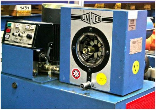
Fig. 14
Device for pressing hose fittings
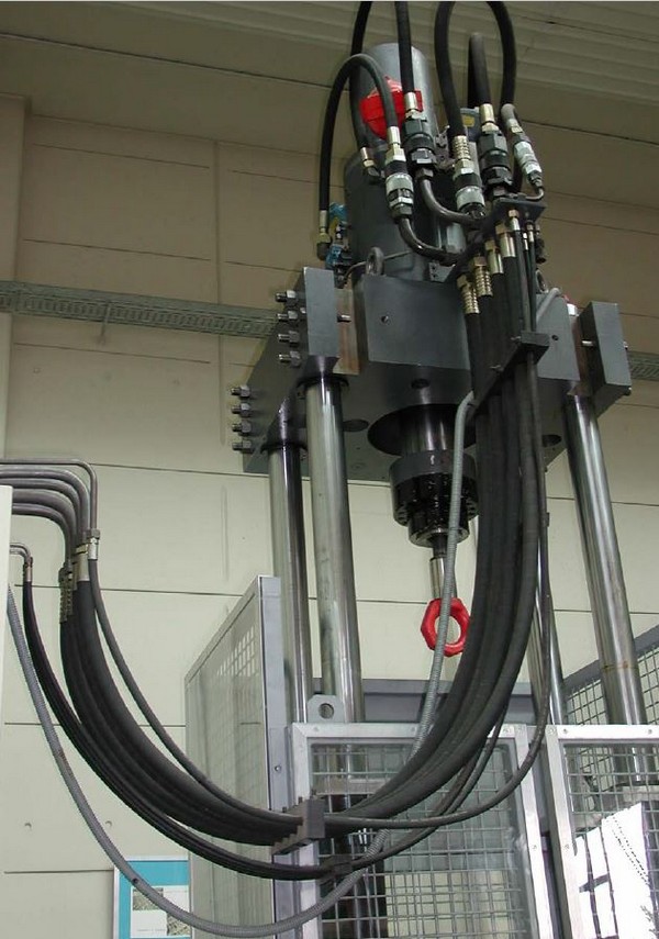
Fig. 15
Hose assemblies in natural position on a test cell
4.3.4 Installing the hose assembly
In order to ensure the functionality of hose assemblies and to not shorten their lifetime due to additional loads, the following has to be observed.
- 1.
Hose assemblies have to be installed in a way that their natural position and movement is not impaired (scour marks have to be avoided), see also figure 15.
- 2.
Hose assemblies must not be subject to tensile, torsional, and compression loads caused by external influences during operation.
- 3.
The smallest bending radius of the hose specified by the manufacturer must not be fallen below.
- 4.
If possible, hose assemblies have to be protected against damage caused by external mechanical, thermal, or chemical influences.
- 5.
Varnishing hose assemblies should be avoided since the outer hose layer may be impaired in its properties of use due to reactions with varnish and the detectability of the marking and possible cracks may be prevented. Hose assemblies should be protected prior to varnishing the machine parts by masking off or a film cover.
- 6.
Possibly present safeguarding measures on the machine have to be re-attached upon installation of the hose assemblies, e. g. safeguarding covers. The initial protected installation position has to be restored.
DGUV Regel 113-020 or DIN 20066 provides an overview of essential installation criteria.
| Note |
|---|---|
| When installing hose assemblies, it is imperative to observe the installation instructions of the hose manufacturer, e g. minimum bending radii. | |
4.3.5 Regular check of hose assemblies
Due to ageing, wear and tear, and damage the hose assemblies have to be checked on a regular basis.
For this, the hose assemblies have to be checked for external deficiencies (visually) by an authorized person (see also TRBS 1203) at least once a year; see also DGUV Regel 113-020. Related specified provisions of the manufacturer have to be observed.
Further notices regarding authorized persons (formerly known as technical experts), tests, and test intervals, see section 7.
These tests have to be documented together with the date in a test log, e. g. when testing the machine (see also TRBS 1201).
The test criteria are:
leakages on the hose, the hose assembly, or the fitting,
the hose coming out of the fitting,
damage or deformations to fittings reducing the functionality and strength of the fittings or of the connection fitting-hose,
damage of the external layer up to the insert (scour marks, cuts, cracks),
embrittlement of the external layer (formation of cracks in the hose material),
deformations not corresponding to the natural shape of the hose assembly, in pressurized or depressurized condition or when being bent, e. g. layer separation, formation of bubbles, pinch points, knees,
corrosion of the fitting reducing the functionality and the strength,
Can the hose assemblies still move freely or are there pinch, shear, or scour points caused by attaching new parts of the system or power units?
Is it ensured that hose assemblies do not project into traffic paths, even when the power units connected via hose assemblies are driven to their respective end positions?
Have hose assemblies been varnished (explanation: cracks and labeling cannot be seen!)?
Have the storage periods and the lifetime been exceeded?
Have all covers been re-mounted after the test?
Are additional stripping protections provided or are they required?
| Note |
|---|---|
| Hose assemblies have to be checked at regular intervals. | |
Hose assemblies shall not be patted by hands when being checked
4.3.6 Faulty hose assemblies
If deficiencies regarding the safe condition of a hose assembly are detected during the test, the relevant hose assembly has to be replaced. Figure 16 shows some faulty hydraulic hose assemblies. Hose assemblies must not be repaired and must not be assembled from old parts.
If several hose assemblies are replaced simultaneously, it has to be ensured that the connections cannot be confused, e. g. by marking them.
| Note |
|---|---|
| Faulty hose assemblies have to be replaced immediately! | |
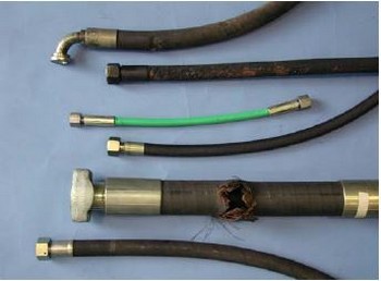
Fig. 16
Examples of failed hydraulic hose assemblies
4.3.7 Lifetime of hose assemblies
Basically, hoses and hose assemblies are subject to a natural ageing process even if they are stored properly (according to section 4.6.2 of DGUV Regel 113-020) and operated under admissible loads. This ageing process reduces the performance of the hose assemblies. Thus, the lifetime of a hose assembly is limited.
The possible lifetime (i.e. period of use) of hose assemblies especially depends on the operation and environmental conditions. Due to the wide range of applications for hose assemblies, it is thus not possible for technical reasons to specify a binding, maximum admissible lifetime in safety rules and regulations and standards.
The instructions of the hose and hose assembly manufacturers regarding the maximum storage time have to be observed. When producing the hose assembly, the hose should not be older than four years.
When determining the lifetime for the corresponding hose assemblies used on a machine, the user first and foremost has to base his decision on the replacement intervals recommended by the machine manufacturer, but also on his or her own experience regarding the individual operating conditions. This especially holds true when the lifetime recommended by the manufacturer is exceeded. Prolonging the lifetime is possible if
corresponding test values and experience on part of the machine manufacturer, the operator or the hose and hose assembly manufacturers are available,
a risk assessment has been conducted and documented by the operator that considered secondary safeguarding measures against hazards caused by hose assembly failures as well, and
the test for safe condition is carried out at appropriate and fixed intervals and by an authorized person.
For the recurring test it should be clarified, if the preconditions that lead to the determination of a certain lifetime have changed, e. g. higher system pressures, changed location of installation. In this case, a risk assessment has to be carried out.
It is absolutely recommendable to shorten the test intervals, e. g. to biannually or quarterly (instead of at least annually), when prolonging the lifetime.
Unless there are other specifications regarding the lifetime of hydraulic hose assemblies, six years are recommended as reference value, see also DGUV Regel 113-020.
4.3.8 Securing the environment in case of hose assembly failures
In general, hose assemblies perform their task without any problems when they are designed and selected properly, produced carefully, and installed correctly.
However, it has to be considered that failures of hose assemblies, e. g. near work stations and traffic paths, can lead to hazards, e. g.:
leakage of hydraulic fluid at high pressure,
lashing, and
fire hazard.
Thus, additional measures for safeguarding the environment in case of hose assembly failures have to be taken at those points, e. g. by means of additional stripping protection or screening (see figure 17).
Special protective hoses for hydraulic hose assemblies can, if properly dimensioned and installed, contribute to a reduction of risks caused by ejected hydraulic fluid jets. The protective hoses must not be closed on both ends in order not to impair their protective effect. The cross-section has to be sufficient. This makes the protective hose to function as intended.
Safeguarding measures against hose assembly failures are not imperative if there is no hazard, e. g. by hose assemblies routed within machine enclosures.
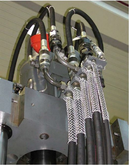
Fig. 17
Stripping protection on hose assemblies
4.3.9 Particularities of plastic hose assemblies
Plastic hose assemblies are used more and more on machines with confined installation conditions, on mobile devices, and in the chemical industry.
Some technological advantages of the plastic hose assemblies can be:
20 to 30 % weight reduction,
reduced external diameter and minimum bending radius,
higher milling and abrasion resistance,
good resistance against diverse chemical substances, as well as
low sensitivity regarding water-containing cooling lubricants,
no or only low influence of ageing during storage time before use,
relatively low price, especially for small nominal widths.
Some technological disadvantages of the plastic hose assemblies can be:
higher breathing volume,
higher loss of elasticity after longer periods of use,
lower torsional strength, thus twisting possible during installation,
higher sensitivity regarding mechanical damage, especially if pressure carriers consist of plastic yarn meshwork,
higher sensitivity regarding UV radiation, thermal radiation, and liquid metal, e. g. welding beads,
higher sensitivity of the external layer regarding cutting oils (however, depending strongly on the material).
The above mentioned advantages and disadvantages of plastic hose assemblies have to be taken into consideration during design, selection, and installation. Regarding lifetime, replacement, and installation, section 4.3.7 applies.
Possible exclusions regarding the use on the part of the manufacturers have to be observed.